47
MF 200 – 300
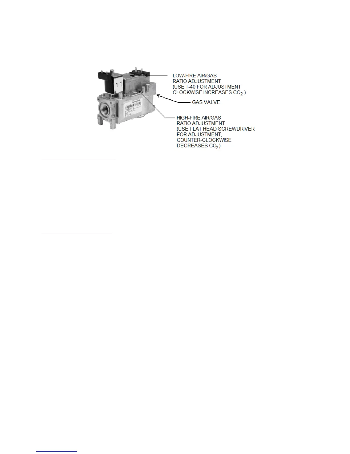
Figure 28: MF 200 – 300 Gas Valve
To adjust the high fire setting
Set the Target Temperature to 190
o
F using the BTC 1 Controller.
Once the appliance is at maximum fan speed locate the high-fire adjustment screw on the top side of the
gas valve. The screw can be identified by a red cylinder casing around the screw. Using a thin flat head
screwdriver turn the screw clockwise to decrease CO
2
levels and counter-clockwise to increase CO
2
levels. Turn the screw 1/4 turn in either way for each adjustment to keep track of the adjustments. After
adjusting the screw wait a moment for the combustion levels to stabilize before attempting to make any
further adjustments. Continue this procedure until combustion levels are satisfied.
Reset the Target Temperature to normal operating conditions on the BTC 1 Controller.
To adjust the low fire setting
Observe the Boiler Inlet Temperature. Set the Boiler Target temperature so that it is 10
o
F above the Boiler
Inlet Temperature. The boiler will begin to modulate to low-fire as setpoint is being reached. The actual
modulation rate will be shown on the screen as Modulation, this will be shown as a percentage. Low-fire
is achieved at 25%.
When this is achieved locate the low fire adjustment screw as illustrated in Figure 27. Using a flat
screwdriver rotate clockwise to increase CO
2
levels and counter-clockwise to decrease CO
2
levels. When
the correct combustion values are achieved replace the screw cap back on to the gas valve.
Reset the Target Temperature to normal operating conditions on the BTC 1 Controller.