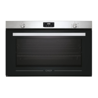
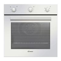
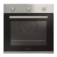
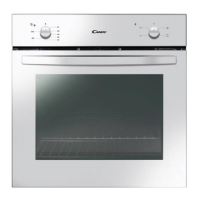
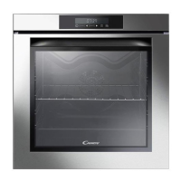
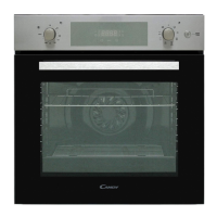
This document is an installation and user manual for Candy Built-In Gas Ovens, specifically models FCG962DX, FCG962DX-19, and FCG962DN-19.
Function Description
The Candy Built-In Gas Oven is designed and manufactured solely for domestic (household) cooking of foodstuffs. Any other use is considered inappropriate and potentially dangerous. The appliance features a gas oven burner for normal convection cooking and a gas grill burner for radiation cooking. Some models are "fan assisted," incorporating a fan motor for forced convection cooking and defrosting. A safety cooling fan motor is integrated to ensure optimal control efficiency, maintain lower surface temperatures, and cool internal components. This fan automatically activates when the oven or grill burner is ignited and may continue to run for several minutes after the burner is turned off.
Important Technical Specifications
- Dimensions: The oven can be fitted into standard units with a width of 90 cm and a depth of 60 cm. Installation requires a compartment as illustrated in figures 1.1a and 1.1b, with minimum dimensions of 860 mm width, 580 mm height, and 550 mm depth.
- Gas Burners:
- Oven Gas Burner: 4.70 kW, located at the bottom, with self-ignition and a safety device.
- Grill Gas Burner: 3.00 kW, located at the top, with self-ignition and a safety device.
- Gas Types: The appliance is supplied for use on LPG (G30/G31 at 28-30/37 mbar or G20/G25 at 20/25 mbar) or Natural Gas (G20 at 20 mbar). Conversion kits for different gas types may be available from After-Sales Service.
- Injectors: Specific injector sizes are required for different gas types. For LPG (G30/G31), the oven injector is 105 (1/100 mm) and the grill injector is 88 (1/100 mm). For Natural Gas (G20/G25), the oven injector is 155 (1/100 mm) and the grill injector is 130 (1/100 mm).
- Air Vent Requirements: Air necessary for gas combustion is calculated as 2 m³/h x kW. For the oven, 9.40 m³/h is required, and for the grill, 6.00 m³/h.
- Electrical Connection: 220-240 V ac, 3 x 0.75 mm² feeder cable (TYPE "H05RR-F" or "H05V2V2-F" resistant to temperatures of 90°C). The earth conductor must be left about 3 cm longer than the others.
- Thermostat Grades: The oven temperature can be regulated from 130°C (or 1) to 240°C (or 10 or Max) for both GAS OVEN and FAN ASSISTED GAS OVEN modes.
- Safety Features:
- Safety valve system: automatically stops gas flow if the flame accidentally extinguishes.
- Cooling fan motor: prevents overheating of controls and internal components.
- Shelf safety catch: prevents shelves from sliding out completely.
- Fan motor safety device (for fan-assisted models): switches off the fan motor if the gas grill control knob is turned on.
- Oven Light: Interior lamp for visual inspection during cooking, energy efficiency class G.
- Rotisserie (some models): Electric motor fitted to the rear of the oven, stainless steel skewer with heatless handgrip and adjustable forks, and a skewer support.
Usage Features
- Control Panel: Features a gas oven/grill thermostat control knob, oven light control knob (or combined with rotisserie/fan motor), and various clock/timer options (60' alarm, 120' alarm, electric clock with minute minder, digital electronic clock with timer).
- Oven Lighting: The oven door must be fully open during ignition. Lightly press and turn the thermostat knob anti-clockwise to the maximum position. Press firmly until the burner lights. If the burner does not ignite within 15 seconds, wait 1 minute before retrying. Manual ignition with a lighted match or taper is possible through opening "A" (fig. 2.3).
- Grill Lighting: The oven door must be fully open during ignition. Lightly press and turn the thermostat knob clockwise to the grill position. Press firmly until the burner lights. If the burner does not ignite within 15 seconds, wait 1 minute before retrying. Manual ignition with a lighted match or taper is possible through the burner pipe (fig. 2.5a).
- Preheating: For correct use of the gas oven, always preheat it (bottom burner) for at least 15 minutes with the oven empty (trays and racks removed).
- Cooking Modes:
- Normal Convection (Gas Oven): Heat produced by the oven gas burner.
- Forced Convection (Fan Assisted Gas Oven - some models): Heat from the oven burner distributed by the fan.
- Radiation (Gas Grill): Heat radiated by the gas grill.
- Ventilation (Defrosting - fan assisted models): Fan only, without oven burner, for defrosting frozen foods.
- Rotisserie Use (some models): Insert the tray into the lowest rack holders, rod support into intermediate holders. Secure meat on the rod with forks. Insert the rod into the side gear opening "P" (fig. 2.10). Remove grip "H", insert shaft "S" into spit motor collar "G". Fit heat shield and switch on grill and turnspit.
- Timers and Alarms:
- 60' / 120' Alarm: Mechanical timers that sound a buzzer but do not switch off the oven or grill. Users must manually turn off the appliance.
- Electric Clock with Minute Minder: 12-hour analog clock and minute minder (max 3 hours) with an acoustic signal. The minute minder is an alarm only and does not switch off the oven or grill.
- Digital Electronic Clock with Timer: 24-hour clock with illuminated display and 99-minute alarm. Features "Touch-control" keys for setting clock, timer, and timer volume. The alarm is an alarm only and does not switch off the oven or grill.
- Oven Thermometer (some models): Provides a general indication of oven heating level (MIN, MED, MAX). For precise temperature, refer to the oven temperature control knob.
- Oven Door: Must be kept closed during grill operation. Becomes very hot during operation; use the handle and keep children away.
Maintenance Features
- General Cleaning:
- Disconnect from electrical supply before cleaning.
- Clean when the appliance is cold, especially enamelled parts.
- Avoid alkaline or acidic substances (lemon juice, vinegar) and cleaning products with chlorine or acidic bases.
- Clean after every use with suitable products.
- Use suitable protective clothing/gloves when handling or cleaning.
- Do not use steam cleaners.
- Do not store flammable material in the oven.
- Do not use harsh abrasive cleaners or sharp metal scrapers on oven door glass or control panel.
- Inside of Oven: Clean after use when cooled down with a mild detergent solution and warm water. Proprietary chemical cleaners may be used after consulting manufacturer recommendations and testing. Avoid abrasive cleaning agents or scouring pads/cloths.
- Enamelled Parts: Clean with a sponge and soapy water or other non-abrasive products. Dry with a microfibre or soft cloth.
- Stainless Steel Surfaces (without anti-fingerprint treatment), Aluminium Parts, Painted or Silk-Screen Printed Surfaces: Clean with an appropriate product and dry thoroughly. Clean very carefully to avoid scratching and abrasion; use a soft cloth and neutral soap.
- Stainless Steel Surfaces (with anti-fingerprint treatment - some models): Clean ONLY with soap/warm water. Do not use abrasive cleaners or abrasive cloths/scouring pads to avoid damaging the special lacquer.
- Oven Fitting Out: Wire racks are assembled with 2 screws. Shelves and trays slide onto guides with a safety catch facing the inside of the oven.
- Grease Filter (fan assisted ovens - some models): A special screen at the back of the oven to catch grease particles, especially when roasting meat. Remove for baking pastry. Clean after any cooking in hot soapy water and dry properly before refitting.
- Replacing Oven Lights:
- Ensure appliance is switched off and cool.
- Switch off electrical supply.
- Remove protective cover (figs. 4.4a - 4.4b).
- Replace halogen lamp with a new one suitable for high temperatures (220-240 V ac, same watt power as original).
- Never replace the lamp with bare hands; use a clean cloth or gloves.
- Refit the protective cover.
- Removing/Refitting Oven Door:
- Removal: Open door fully (fig. 4.5). Open levers "A" on left and right hinges (fig. 4.6). Hold door as shown in fig. 4.7. Gently close door (fig. 4.8) until levers "A" hook to part "B" of the door. Withdraw hinge hooks following arrow "C" (fig. 4.9). Rest door on a soft surface.
- Refitting: Hold door firmly (fig. 4.10). Insert hinge tongues into slots, ensuring groove drops into place (fig. 4.11). Open door to full extent. Fully close levers "A" (fig. 4.12). Close door and check it is properly in place.
- Gas Taps Lubrication: In case of difficulty in operation, call Service.
- Injector Replacement: Lift and remove the lower panel. Unlock safety valve probe "V" and ignition electrode "E". Unscrew and remove burner securing screw "A". Withdraw burner. Unscrew injector with a 7 mm box spanner and replace with a new one according to the "Table for the choice of the injectors". Regulate air supply.
- Air Supply Regulation: Slacken screws "A" securing air flow regulation collar "B" (fig. 2.6). Move collar forward or backward to increase or reduce air aperture according to gas type. If collar "B" is not fitted, fold it around the burner with the throttled section oriented toward the burner deflector.
- Oven Burner Minimum Adjustment: Remove control panel (fig. 2.8). Remount knob, turn on oven burner to maximum. Remove knob, unscrew by-pass screw "G" (fig. 2.7) about three times. Remount knob, preheat oven for 15 minutes, then set knob to minimum. Remove knob, slowly screw by-pass screw "G" until a 3-4 mm flame height is obtained. Refit control panel and knobs. For G30/G31 (LPG), the by-pass screw must be fixed thoroughly.