No. Parts Name
17 Power supply
18 Power switch
19 Chassis
20 Power supply duct
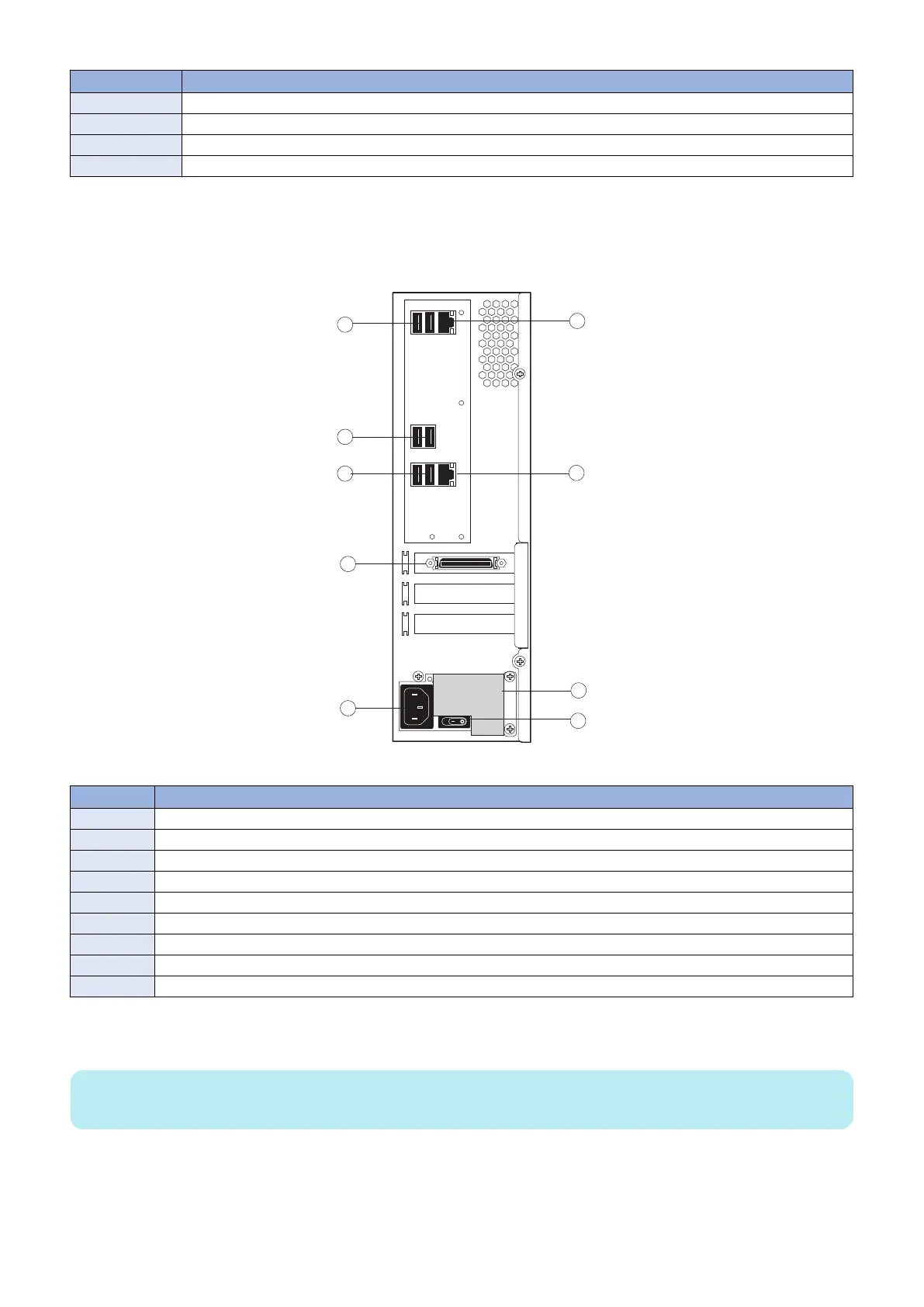
■ imagePRESS Server connector panel and LED diagnostic codest
The connector panel of the imagePRESS Server has the external connectors and power switch. Familiarize yourself with the
connector panel of the imagePRESS Server.
Figure 5: imagePRESS Server connector panel
No. Name
1 Type A USB2.0 ports (x2)
2 Type A USB2.0 ports (x2)
3 Type A USB3.0 ports (x2)
4 Printer interface connector
5 Power connector
6 Network port (Upper RJ-45)
7 Crossover Ethernet connector
8 Duct
9 Power switch
During startup, the imagePRESS Server advances through a standard diagnostic sequence. Each diagnostic code flashes rapidly
on the LED display during this sequence, until the imagePRESS Server reaches Idle. At Idle, the LED display shows the 00 code.
NOTE:
The LED display is mounted in upside-down orientation.
3. REPLACING PARTS
17