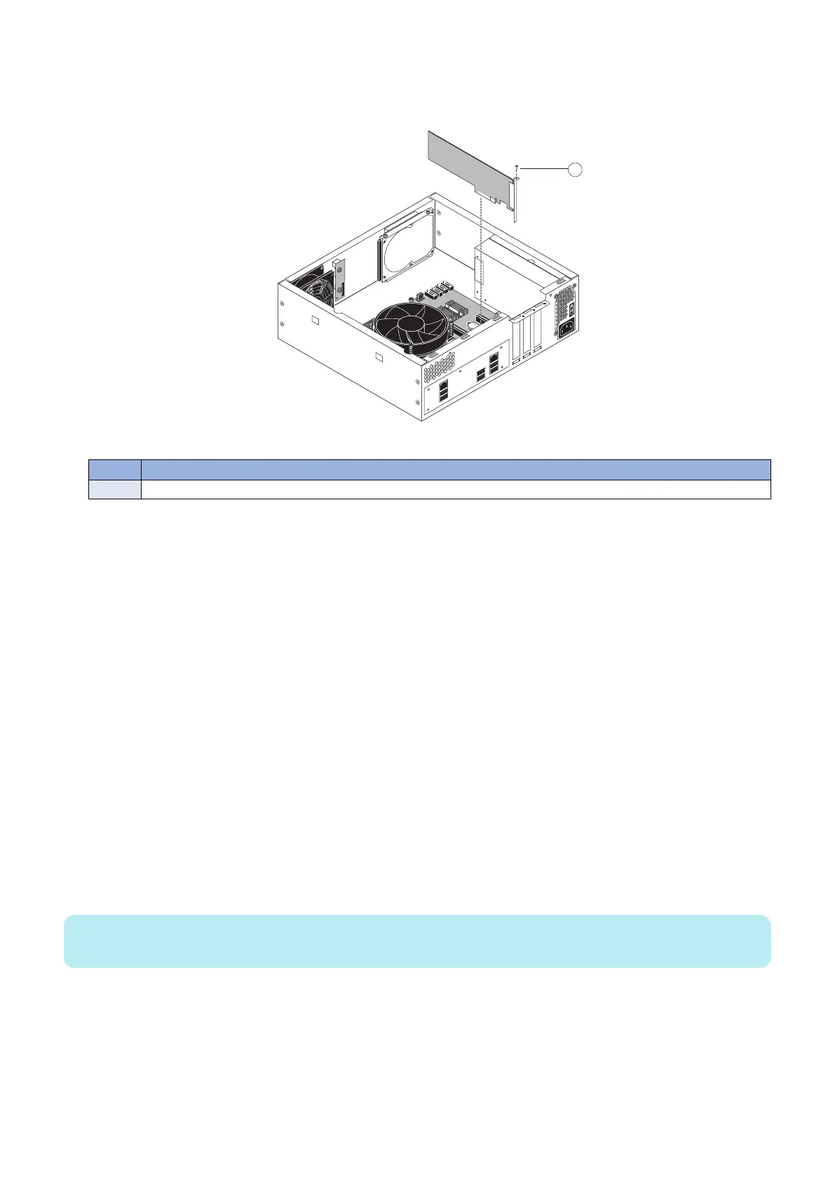
3. Remove the mounting screw that secures the printer interface board to the imagePRESS Server chassis (see figure
below).
Set aside the mounting screw so that you can replace it later.
Figure 10: Removing the printer interface board
No. Name
1 Mounting screw
4. Remove the printer interface board from the motherboard.
Gently pull the printer interface board straight out of the PCIE x16 slot on the motherboard. Place the printer interface board
on an antistatic surface.
● To replace the printer interface board
1. Firmly seat the printer interface board in PCIE x16 slot on the motherboard. For the location of PCIE x16 slot, see
“Motherboard jumpers” on page 25. The printer interface board is keyed to fit only one way.
2. Replace the mounting screw that secures the printer interface board to the chassis.
Insert the mounting screw through the chassis and into the hole on the board mounting bracket (see “To remove the printer
interface board” on page 21). Tighten the screw completely.
3. Connect one end of the 10-pin power button cable to J351 connector on the printer interface board. Connect the
other end to the J11 connector on the motherboard.
The cable connector is keyed to fit only one way.
4. Reassemble the imagePRESS Server and verify its functionality (see “Restoring imagePRESS Server functionality
after service” on page 43).
■ DIMM
DIMM (dual in-line memory module) is held in place by a lever at the end of DIMM-A0 slot. The motherboard contains two DIMM
slots, DIMM-A0 and DIMM-B0 (see “Motherboard jumpers” on page 25).
NOTE:
Approved DIMMs are available from your authorized service/support center.
● To replace a DIMM
1. Access and open the imagePRESS Server, as described on “Accessing the imagePRESS Server” on page 18.
3. REPLACING PARTS
22