26 ir33 platform “connections” +030220445 - rel. 2.3 - 27.04.2011
111
70.4
60
H
ACCP
DIN
Fig. 7.a
ENGLISH
7. IR33DIN
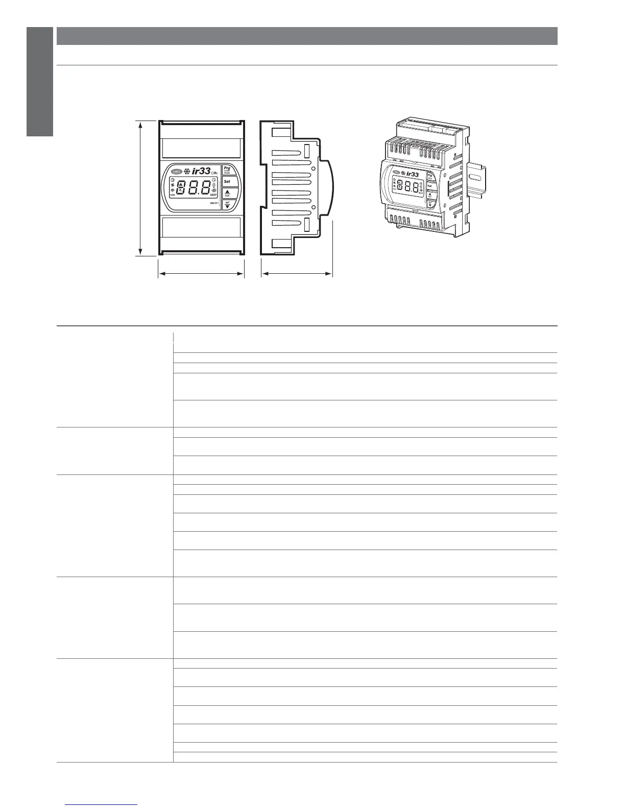
7.1 Dimensions
The dimensions of the ir33DIN are 60x111x70.4 mm for all versions, with the drilling template measuring 40x70 mm.
DIN rail assembly
7.2 Electrical specifi cations
voltage power
Power supply
model E: 230 V~ 50/60 Hz; 3 VA, 25 mA~ max
model A: 115 V~ 50/60 Hz; 3 VA, 50 mA~ max
model H: 115-230 V~ 50/60 Hz; 6 VA, 50 mA~ max
model L: 12...24 V~ 50/60 Hz; 4 VA, 300 mA~ max
12 Vdc, 12 - 30 Vdc TR ADR4W012 transformer, 315 mA slow-blo w fuse in secondar y,
only use SELV power supply
model O: 12 V~ 50/60 Hz; 4 VA, 300 mA~ max
12 Vdc, 12 - 18 Vdc TRADR4W012 transformer, 315 mA slow-blow fuse in secondary,
only use SELV power supply
Insulation guaranteed by the power
supply
voltage power
model E, A, H:
insulation from very low voltage parts: reinforced; 6 mm air, 8 mm surface; 3750 V insulation
insulation from relay outputs: basic; 3 mm air, 4 mm surface; 1250 V insulation
model O, L: insulation from very low voltage parts: to be guaranteed externally by safety transformer
insulation from relay outputs: basic; 6 mm air, 8 mm surface; 3750 V insulation
Inputs S1 NTC or PTC, depending on the model
S2 NTC or PTC, depending on the model
DI1 voltage-free contact, contact resistance < 10 ohm, closing current 6 mA
S3 NTC or PTC, depending on the model
DI2 voltage-free contact, contact resistance < 10 ohm, closing current 6 mA
S4 NTC or PTC, depending on the model
DI3 voltage-free contact, contact resistance < 10 ohm, closing current 6 mA
S5 NTC or PTC, depending on the model
Maximum distance between probes and digital inputs less than 10 m
Note: in the installation, keep the power supply and load connections separate from the probe, digital inputs, repeater display and supervisor
cables.
Type of probe Std. Carel NTC 10 k at 25 °C, range -50 to 90 °C
measurement error: 1 °C in the range -50 to 50 °C
3 °C in the range +50 to 90 °C
High temperature NTC 50 k a 25 °C, range -40 to 150 °C
measurement error: 1.5 °C in the range -20 to 115 °C
4 °C in the range outside of -20 to 115 °C
Std. Carel PTC (specifi c model) 985 at 25°C, range -50 to 150 °C
measurement error: 2 °C in the range -50 to 50 °C
4 °C in the range +50 to 150 °C
Relay outputs depending on the model
8 A (*) EN60730-1: 250 V~ 8(4) A on N.O., 6(4) A on N.C., 2(2) A on N.O. and N.C.; 100,000 operating cycles
UL 873: 250 V~ 8A res 2FLA 12LRA C300; 30,000 operating cycles
16 A (*) EN60730-1: 250 V~ 10(4) on up to 60 °C on N.O., 12(2) A on N.O. and N.C.; 100,000 operating cycles
UL 873: 250 V~ 12A res 5FLA 30LRA C300; 30,000 operating cycles
2HP EN60730-1: 250 V~ 10 (10) A; 100,000 operating cycles
UL 873: 250 V~ 12A res 12FLA 72LRA; 30,000 operating cycles
(*): Relay not suitable for fl uorescent loads (neon lights, ...) that use starters (ballasts) with phase-shift capacitors. Fluorescent lamps with
electronic control devices or without phase-shift capacitors can be used, within the operating limits specifi ed for each type of relay.
insulation from very low voltage parts reinforced; 6 mm air, 8 mm surface; 3750 V insulation
insulation between the separate relay outputs basic; 3 mm air, 4 mm surface; 1250 V insulation
 Loading...