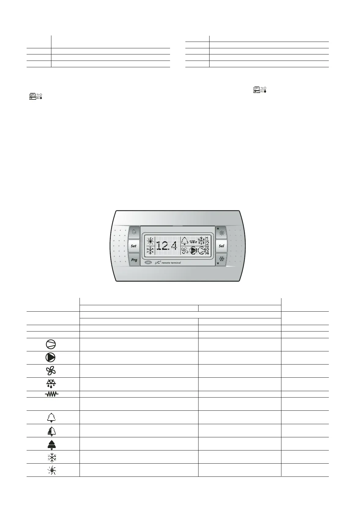
Informazioni visualizzate (Fig 7.10.7):
Riga display Significato
1 Versione firmware terminale
2 Versione firmware µC
2
3 Indirizzo supervisore del µC
2
4 Tasso di errore percentuale relativo alla comunicaz. tra term. e µC
2
Tab 7.10.3
Nel caso sia collegata la linea RS485 del supervisore tramite l’adattatore
MCH200TSV0 ed il supervisore sia attivo, appare in alto a destra l’icona
“ ”; i due pallini a destra delle scritte Rx, Tx indicano rispettivamente
i messaggi di richiesta inviati dal supervisore al µC
2
di indirizzo H10 (Rx)
e le trasmissioni di risposta da parte del µC
2
(Tx): pallino vuoto = nessuna
trasmissione (dati invariati), pallino pieno = dati trasmessi.
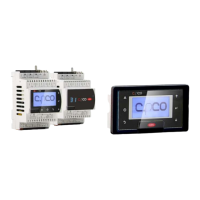
Collegamento alla rete di supervisione (MCH200TSV0)
Qualora si desideri collegare il µC
2
al terminale remoto MC2000TX00 senza
perdere la connettibilità alla rete di supervisione, è necessario installare
l’adattatore seriale (opzionale) MCH200TSV0, come indicato in Fig.7.10.1.
Disconnettere il connettore telefonico, aprire la finestrella che copre il
pin-strip a 15 vie, utilizzando un tronchese appuntito, inserire l’adattatore
da pin-strip a plug 4 vie, rispettando il verso indicato in Fig 7.10.1 (pin
1 a sinistra dal lato del triangolo). Eseguire il collegamento della rete
RS485 al convertitore ed impostare il parametro H10 (indirizzo seriale)
del µC
2
al valore desiderato.
Information displayed (Fig 7.10.7):
Display row Meaning
1 Terminal firmware version
2µC
2
firmware version
3 Supervisor address of the µC
2
4 Percentage error rate in the communic. between the term. and µC
2
Tab 7.10.3
If the RS485 supervisor line is connected via the MCH200TSV0 adapter
and the supervisor is active, the “ ” icon is displayed at the top
right; the two circles to the right of the Rx, Tx fields indicate
respectively the request messages sent by the supervisor to the µC
2
with address H10 (Rx) and the response from the µC
2
(Tx): empty
circle = no data sent (data unchanged), full circle = data sent.
Connection to the supervisor network (MCH200TSV0)
To connect the µC
2
to the remote terminal MC2000TX00 while still
maintaining the possibility to connect to the supervisor network, the serial
adapter (optional) MCH200TSV0 must be used, as shown in Fig. 7.10.1.
Disconnect the telephone connector, open the cover on the 15-way pin
strip using a small pair of wire cutters, and insert the adapter (pin-strip
to 4-pin plug), in the direction shown in Fig 7.10.1 (pin 1 on the left
from the side of the triangle). Connect the RS485 network to the
converter and set the parameter H10 (serial address) of the µC
2
to the
desired value.
80
µC
2
- cod. +030220420 - rel. 2.0 - 18.10.04
Simbolo Significato Circuito frigorifero
Acceso Lampeggiante interessato
Symbol Meaning Refrigerant circuit
ON Flashing involved
1,2 Compressore 1 e/o 2 acceso/
Compressor 1 and/or 2 ON
Richiesta di accensione/
Start request
1
3,4 Compressore 3 e/o 4 acceso/
Compressor 3 and/or 4 ON
Richiesta di accensione/
Start request
2
Almeno un compressore acceso 1 e/o 2
At least one compressor ON 1 and/or 2
Pompa/ventilatore aria mandata accesa/o Richiesta di accensione 1 e/o 2
Pump/air outlet fan ON Start request 1 and/or 2
Ventilatore di condensazione attivato 1 e/o 2
Condenser fan ON 1 and/or 2
Sbrinamento attivo Richiesta di sbrinamento 1 e/o 2
Defrost active Defrost request 1 and/or 2
Resistenza attivata/
Heater ON
Richiesta di accensione/
Start request
1 e/o 2/
1 and/or 2
Tasto alarm LED rosso Allarme attivo 1 e/o 2
Alarm button Red LED Alarm active 1 and/or 2
Allarme attivo Allarme EEPROM 1 e/o 2
Alarm active EEPROM alarm 1 and/or 2
Relè avviso attivato (solo con scheda espansione)
Warning relay activated (only with expansion board)
Relè allarme attivato
Alarm relay activated
Modalità Pompa di Calore (P6=0) Richiesta cambio di stagione 1 e 2
Heat pump mode (P6=0) Season changeover request 1 and 2
Modalità Refrigeratore (P6=0) Richiesta cambio di stagione 1 e 2
Chiller mode (P6=0) Season changeover request 1 and 2
Tab.7.10.4
Fig. 7.10.7
Interfaccia utente/
User interface