Carel srl: pCO Stage Controller
page 13
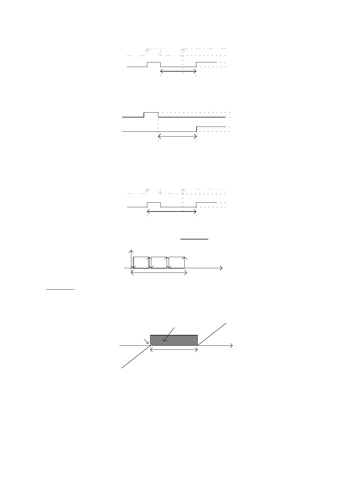
It sets the turning off minimum time of the circuit 1 devices. When after the last turning off the selected minimum has
not alapsed, the circuit 1 devices are not turned on again.
ON
OFF
P11
ON
OFF
request
device
Fig. 8
P12 - minimum time between successive probe 2 devices
It represents the minimum time (in seconds) that must elapse between the turning on of a device and the turning on of
the subsequent device controlled by the probe 1. This parameter allows to avoid simultaneous starting of the devices.
ON
OFF
P12
ON
OFF
device 1
device n
Fig. 9
P13 - minimum time between successive turning on of the same device of the probe 1
It sets the minimum time (in seconds) that must elapse between successive turning on of the device, independently
of the detected measurement and of the setpoint. Selecting this parameter it is possible to restrict the turning on
number per hour. For example, if the maximum allowed number of insertions is 10, selecting a value of 360 seconds
allows to stay within established this limit.
ON
OFF
P13
ON
OFF
request
device
Fig. 10
P14, P29 regulation with “lateral band” or “neutral zone”
They indicate the activation of the connected devices. In lateral band the devices are positioned proportionally
within the controlled zone. Example with 3 devices on a single circuit.
value measuredsetpoint differential
dev. 1 dev. 2 dev. 3
3 devices
in the same circuit
Fig. 11
In neutral zone there is a zone where no device is activated or deactivated.
The activation point of the devices is when the detected measure exceeds the neutral zone (detected
measure>set+differential). The number of the devices to be activated depends on the time elapsed in this condition.
The device switch off takes place when the detected measure goes down below the neutral zone (detected measure
<set), and in this case too it depends on the time. See timing P17, P32 and P18, P33.
value measured
setpoint
differential
dev. 1
dev. 2
dev. 3
dev. 1
dev. 2
dev. 3
energize
deenergize
neutral zone
Fig. 12
P15, P30 - regulation type
Indicate the regulation of the circuit 1 and 2 respectively. This parameter is valid only when the control with lateral
band of regulation is chosen (P14=1 and P29=1). The regulation may be Proportional or Proportional + Integral.
P16, P31 - integration time
Indicate the time of integration when a Proportional + Integral type of control has been chosen (P15=1 and P30=1).
P17, P32 - time between requests of switch on
The two parameters allow, respectively, the selection of time between the successive requests of switch on of the
devices controlled by the probe 1 and 2.

 Loading...


