Carel srl: pCO Stage Controller
page 14
These parameters are present only if the control of the devices is of neutral-zone type.
P18, P33 - time between turn off requests
The two parameters allow, respectively, the selection of time between the successive requests of turn Off of the devices
controlled by the probe 1 and 2. These parameters are present only if the control of the devices is of the neutral-zone type.
P19, P34 - selection of the device rotation
The two parameters allow the enabling to the rotation of the devices controlled by the probe 1 and 2.
The implemented rotation is of the “FIFO” type: the first On is the first Off.
P20 - selection of the device no. 1/valve inverter
Enables the presence of the inverter on the device no.1, controlled by the probe 1, or of a 0-10 volt valve, depending
on the presence of neutral-zone or lateral-band regulation. The parameter is displayed only if P1>0 and P4>0 and if
the functions “Number of circuit 1 voltage control” and “Neutral Zone” have not been enabled at the same time (P6>0
and P14=0). Therefore the cases in which the parameter is displayed are: P1>0, P4>0, P6=0, P14=0;
P1>0, P4>0, P6>0, P14=1.
case 1 - presence of lateral-band regulation
The control involves the selection of a setpoint (SI1) and a differential (d3). When the value detected by the probe 1
is less than or the same as the value of the valve setpoint, there are 0 volts at the output dedicated to this device. As
the value detected by the probe 2 deviates from the set point, the analog output increases in proportion to the
deviation, and reaches 10 volts when the detected value is the same or higher compared to the setpoint +
differential.
differential
setpoint
device 1
value measured
probe 1
Volt
0
10
device 1
Fig. 13
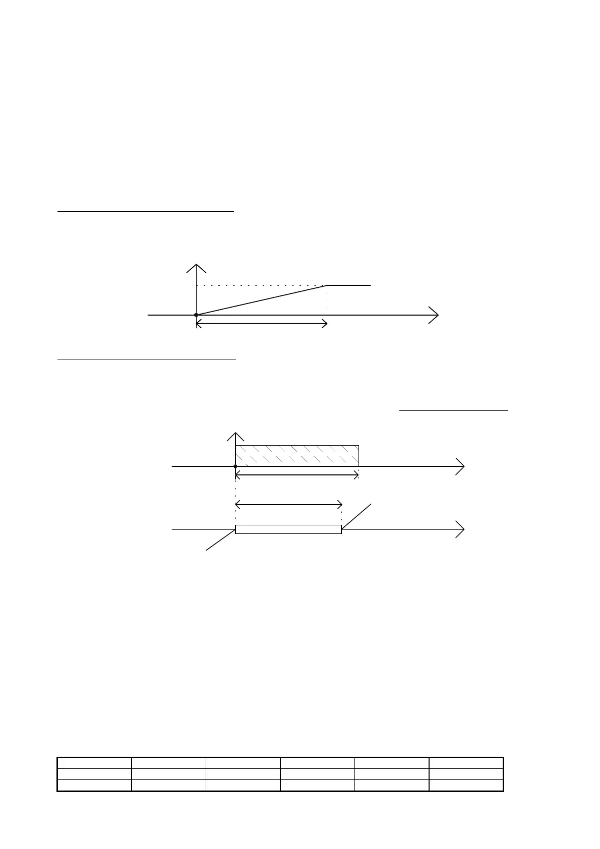
case 2 - presence of neutral-zone regulation
The control requires the solution of a deviation (Sr2) from the setpoint. The output of the device 1 inverter increases
when the reading of the probe 1 exceeds the value of the neutral zone setpoint St1 + the display of the device 1
inverter (Sr2). The decrease takes place when the probe 1 reading is below the value of the neutral-zone setpoint. In
the zone included between the neutral-zone set point and the neutral zone setpoint + deviation of the device 1
inverter, the inverter output does not change at all; for this reason the zone is called neutral zone of the inverter. The
output of the inverter increases/decreases at each cycle of the programme - i.e. about every second - of a value that
can be selected named inverter step (Sr1).
offset
inverter
setpoint
neutral zone
device 1
differential neutral zone
neutral zone
inverter increase zone
inverter decrease zone
inverter neutral zone
devices
value measured
probe 1
devices
value measured
probe 1
Fig. 14
Caution:
when the device no.1/valve inverter is enabled and the regulation takes place with neutral zone, the
activation of the devices occurs as follows:
- the device no.1, which is controlled by the inverter, is activated as soon as turn on is needed;
- if the request remains, the output of the device no.1 inverter is increased;
- if the request is still present, and the output of the inverter reaches 10 volts, the other devices are required one at
a time, with rotation (when selected) and according to the timing.
The turn off stage occurs as follows:
- the inverter output is decreased;
- when the inverter output has already reached 0 volts, the other devices turn off, one at a time, according to the
timing and rotation;
- the last device being turned off is the no.1.
P21 - selection of the analog input through setpoint variation (see fig. 30)
The sepoint of the devices managed by the probe 1 can be selected by means of a potentiometer connected to the
B3-AVSS terminals. This is possible if the parameter P21 equals 1. The table shows some analog-inspect resistive
values (ohm) to be given to obtain the respective values in bar, in °C or in °F depending on the unit of measure of
choice.
bar/°C/°F Kohm bar/°C/°F Kohm bar/°C/°F Kohm
-20 67.71 0 27.28 20 12.09
-15 53.39 5 22.05 25 10.00

 Loading...


