Model 99FRD, 100CRD & 102CRD oil burners — Instruction manual
Carlin part number MN99102 Rev. 08/20/08
– 10 –
3. Prepare burner (continued)
Inspect the nozzle adapter before replacing the nozzle. If the
threads have been damaged or show score marks, replace
the nozzle line/adapter assembly.
4. Replace the retention ring assembly by slipping one of the riveted arms
throughthegapbetweentheelectrodetips.Alignthisarmstraightup,
with the ring clamp firmly against the nozzle adapter shoulder (see
Figure10).Thentightentheclampingscrew.
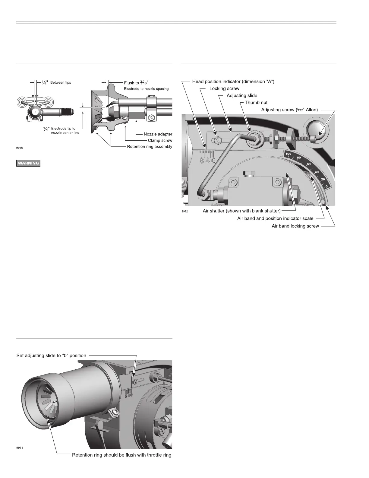
5. Repositionandchecktheelectrodesettings.Positiontheelectrodesas
showninFigure10.Thesesettingsarecriticalinensuringareliable
ignition.Oncetheelectrodesareset,checkallclampstobesurethey
are securely tightened.
6. Insertthecombustionhead/nozzleassemblyintheburner.
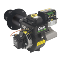
Check zero position (99FRD & 100CRD only)
1. SeeFigures11,12and13.Loosentheoillinethumbnutandadjusting
slide locking screw. Use a B\cx"Allenwrenchtorotatetheadjusting
screwuntiltheleadedgeoftheslidealignsto“0”onthescale.The
retentionringshould beush, ornearlyush,with theedgeof the
throttling ring.
2. Iftheretentionringisnotclosetoushwiththethrottlering,make
sure the air tube is completely inserted into the housing collar and the
Set initial burner air settings
Combustionhead
1. The combustion head adjusting slide controls the spacing between the
retention ring and throttle ring (or air cone), regulating how much air
passes around the retention ring.
2. Loosen the oil line thumb nut and adjusting slide locking screw. Use a
B\cx"Allenwrenchtorotatetheadjustingscrewuntiltheleadedgeof
theslidealignstothenumbergiveninTable3,page11.Lockinplace
by first tightening the oil line thumbnut, then tightening the locking
screw.
Airshutter
1. Theairshutterisxedforall99FRD,100CRDand102CRDburners.
Seepage7forthecorrectairshuttertype.(Some102CRDburners
maybeequippedwith3-slotairshutters.)
Airband
1. The air band is marked in percent opening. Loosen the air band locking
screw and move the air band until the pointer lines up with the percent
openinggiveninTable3,page11.
Final adjustments
1. The burner is now adjusted to the approximate air settings for the firing
ratechosen.Whenyoucheckcombustionwithinstrumentsduringstart-
up or servicing, you may have to adjust the head slightly to achieve the
desiredefciency.See“Adjustburnerusingtestinstruments,”page22.
(Notethatpressureoverrewillreduceairow,requiringmoreair
opening.)
Figure 11 Check zero position — 99FRD & 100CRD only
Figure 10 Combustion head/nozzle/electrode settings Figure 12 Combustion head and air band adjutsments