Model 99FRD, 100CRD, & 102CRD oil burners — Instruction manual
Carlin part number MN99102 Rev. 08/20/08
– 9 –
3. Prepare burner
Removing/installing head assembly
Use care when handling burner components after the burner
hasbeenring.Componentscanbehotandcouldcause
severe personal injury.
You will need to remove the combustion head assembly for inspection of
the assembly, replacement of the oil nozzle or adjustment of electrodes.
To remove the assembly:
1. Loosen, and then rotate the two screw clamps securing the ignitor in
place.Swingtheignitorplateopen.
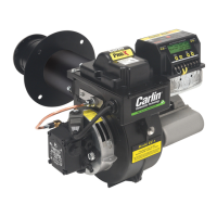
2. See Figure 7. Remove theblowershieldbylooseningthe retaining
screw on its front edge if needed for easier removal or insertion of the
combustion head assembly.
3. Unscrewtheoillinettingandthumbnutattheburnerhousing.
4. Pull the threaded end of the oil tube into the blower housing.
5. SeeFigure7. Rotate thecombustion head assembly 180° so the
electrodes are upside down. This places the electrode insulators out
of the way for easy removal.
6. Removethecombustionheadassemblybypullingtheassemblyup
and out of the housing.
7. Handletheassemblywithcaretoavoidbending/movingtheelectrodes,
or damaging the electrode ceramic insulators.
8. Inspect the gasket on the bottom of the ignitor plate. The gasket prevents
air from escaping from the housing. Replace the gasket if not in good
condition.
9. Inspecttheignitorcontactclips.Cleanorreplaceifnecessarytoensure
reliable contact with the electrodes.
Install nozzle/check electrodes
1. Loosentheclampscrewontheretentionringassembly(seeFigure10,
page10).Slidetheretentionringassemblyoffofthenozzleadapter.
Then loosen electrodes to rotate out of the way.
2. Install and tighten the nozzle shown inTable 1, page 3, for retrot
applications. Install the nozzle given in the appliance manual when
applicationinformationforthe99FRD,100CRD,and102CRDoilburner
is given.
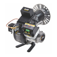
3. Holdthenozzleadaptersecurelywhenremovingorreplacingthenozzle
(Figure 9). Take care not to damage the electrode insulators or to bend
the electrodes in the process.
To replace the combustion head assembly, reverse the sequence.
• Remember to put the assemblyin upside down, so the electrode
insulators are out of the way. Remove, then replace, the blower shield
if necessary for easier removal/insertion of the assembly.
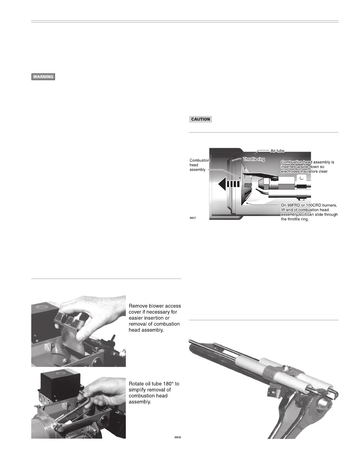
• SeeFigure8.For99FRDor100CRDburners,youwillhavetoliftthe
end of the assembly to guide it through the throttle at the end of the
airtube.DONOTFORCE.
Use care when tightening the oil line fitting to oil tube extension.
Tighten securely, but do not cross-thread or over-tighten.
Figure 8 Inserting combustion head assembly
Figure 7 Removing/inserting combustion head assembly
Figure 9 Carefully support the nozzle adapter when
installing or removing nozzle