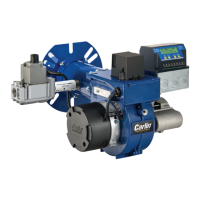
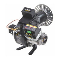
Model 99FRD, 100CRD & 102CRD oil burners — Instruction manual
Carlin part number MN99102 Rev. 08/20/08
– 22 –
5. Adjustment and verication
Adjust burner using test instruments
1. Operateburnerfor15minutesbeforemakingnaladjustmentsusing
test equipment.
2. Checkforleaksinfuelpiping.
Inspect fuel piping system for leaks. Repair any leaks to avoid
fire hazard from oil leakage or combustion problems due to
air infiltration into oil.
3. Inspectame
• Look atame through appliance combustion chamberobservation
port.Theameshouldbewell-denedandshouldnotimpingeonany
appliancesurface.(Ifyoumakeairchangeslater,inspecttheame
again.)
Donotattempttoconrmcombustionsimplybyinspecting
theamevisually.Youmustusecombustiontestinstruments.
Failure to properly verify/adjust combustion could allow unsafe
operation of the burner, resulting in severe personal injury,
death or substantial property damage.
1. Inserttestprobeintoventsampleopeningtosampleueproducts.
2. Withthe99FRD,100CRD,or102CRDburnerequippedwiththecor-
rectoilnozzle,headsettingandairbandsetting,theueproductswill
usuallycontainbetween11½%and12½%CO
2
(5.9%and3.8%O
2
)
andzero(Bacharach)smoke.
3. Usecombustiontestequipmenttoverifythatburnerisproperlysetup
foryourinstallation,withintherangelistedinTable3.Applianceswith
positivepressureinthechambermayrequireawiderairopening.See
appliance instructions for details. Verify/adjust settings by testing with
instruments.
a. Checksmoke.ItshouldbezeroontheBacharachscale.
b. Settheapplianceuedamperorbarometricdraftregulatorsothedraftor
pressureintheventcomplieswiththeappliancemanufacturer’sinstruc-
tions.
Heatingunitsdesignedfornaturaldraftoperationarenormally
setforaslightlynegativepressure,usually–0.01to–0.02
inchesw.c.draftatthecombustionchambertestport.Ap-
pliances designed for forced draft (positive pressure in the
chamber) must be air-tight to prevent exfiltration of harmful
combustion products. Failure to properly set draft for the
appliance could result in severe personal injury or death.
c. CheckpercentofCO
2
(orO
2
). Fine tune the burner, if necessary, by slightly
adjusting the head position for more or less air.
d. Rechecksmoke(shouldbezero)andueorchamberpressure/draft(adjust
if necessary and retest).
Allinstallationsshouldbecheckedafteronetotwoweeksof
operation to ensure the appliance/burner units are operating
correctly.
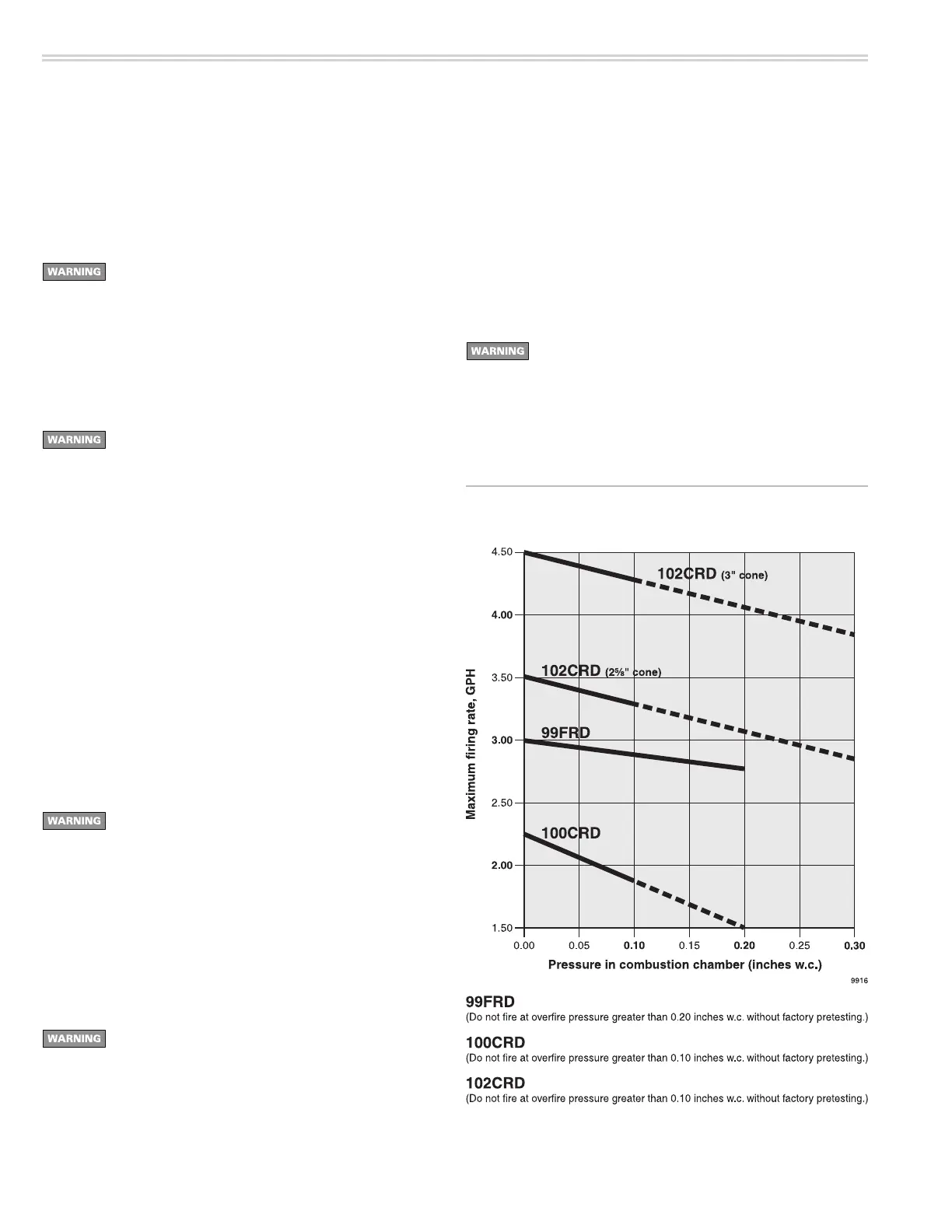
Figure 20 Maximum firing rate decreases as overfire
pressure increases
Firing against positive overfire pressure
1. Burner ratingmaximuminputs arebasedon operationwithzero to
slightlynegativepressureoverre,typically0.01to0.03inchesw.c.
2. Whenaburnerisappliedtoanappliancethatoperateswithahigher
pressure overfire, the maximum firing rate decreases because the
maximumavailableairowfromtheburnerblowerdecreases.
3. ReadthegraphbelowinFigure20tondthemaximumburnerring
rate at positive overfire pressures.
Donotapplya99FRD,100CRDor102CRDburneratapres-
surehigherthanlistedinFigure20unlesstheapplication
has been factory pretested.