Model 99FRD, 100CRD & 102CRD oil burners — Instruction manual
Carlin part number MN99102 Rev. 08/20/08
– 12 –
3. Prepare burner (continued)
• Thenozzlelineheaterneedspowerwhentheburnerisinstandby(no
call for heat from the appliance). Make sure the nozzle line heater is
powereddirectlyfromthe120VACHOTline,notthroughtheappliance
operating control circuit. The nozzle line heater wiring should be shown
on the wiring diagram supplied with the appliance/burner unit.
• Thenozzlelineheaterissuppliedwithanelectricaldisconnectharness,
allowing removal of the combustion head assembly without discon-
necting wires. Position the heater harness disconnect in the rear of
the blower housing, above the blower access cover. The wire leads to
the disconnect route through the side of the housing into the junction
box.
Whenrststartingtheburner,oraftertheserviceswitchhas
beenoffforsometime,theheaterrequiresabout15minutes
to bring the oil to operating temperature.
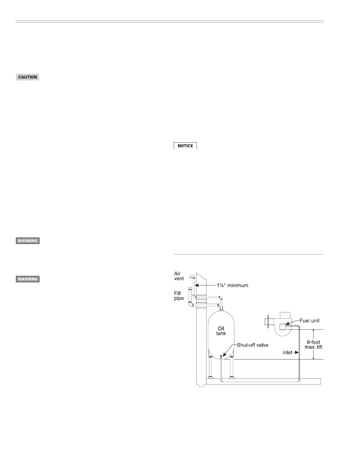
Figure 14 One-line fuel system
One-line fuel system requirements
SeeFigure14.Thestandardburnerfuelunitisasingle-stage,3450-RPM
oilpump.Applythisfuelunitonlyonone-linesystemswherethefuelsup-
ply is on the same level with, or higher than, the burner. This ensures oil
owbygravity.Alsomakesurethetotalliftdoesnotexceed8feet(height
difference from bottom of oil tank to fuel unit). For other conditions, you
must provide a two-line fuel system. You may also have to change the fuel
unit to a two-stage type.
Inspect/install fuel supply
Inspect the oil supply system. Ensure that the fuel lines are
correctlysizedandinstalledandthatthefuelowisunob-
structed,theoiltankiscleanandonly#1or#2heatingoil
aresupplied.Failuretosupplyareliableoilowcouldresult
in loss of heat and potential severe equipment damage.
Nozzle line heater
• Oilburnersoftenoperateinspaceswheretemperaturestend tobe
cool,typically60°Forlower.Cooloilhashigherviscosity,whichcan
affect atomization, ignition, combustion and fuel consumption. The
nozzle line heater avoids this problem by heating the nozzle line oil to
between120°Fand130°F,resultinginsmootherignitionandimproved
combustion.
General guidelines:
• Wheninstallingoillines, use continuous runsofheavy-wallcopper
tubing if possible.
• Checkfuelunit(oilpump)datasheetforrecommendedlinesizing,lift
limitations and maximum length.
• Checkallconnectionsandjointstoensuretheyareair-tight.
• Usearettings.DoNOTusecompressionttings.
• Neverusepipesealingtape.Fragmentscanbreakoffandplugfuelline
components.
• Installashut-offvalveatthetankandoneneartheburner.(Usefusible
handle design valves when possible or when required by codes.)
• Installalargecapacityfuellter(ratedfor50micronsorless)nearthe
burner.
Fuel unit bypass plug
The fuel unit is shipped with its bypass plug not installed,
intended for a one-line oil system. Install the bypass plug only
ifconnectingtoatwo-lineoilsystem.Operatingwiththeplug
in place on a one-line system will damage the fuel unit and
could lead to oil leakage and fire hazard.
Ifthefuellineorfuelsupplyisaboveburner,neverexceed3
PSIGpressureatthefuelunitinlet.InstallasuitableOSVto
reducethepressure.Operatingthefuelunitwithhigherinlet
pressure could result in fuel unit seal damage, oil leakage
and potential fire hazard.