Motor Controllers AC Variable Frequency Drives Type VariFlex
3
RVLF
Specications are subject to change without notice. Pictures are just an example. For special features and/or customization, please ask to our sales network. 13/12/2017 225
5. Troubleshooting
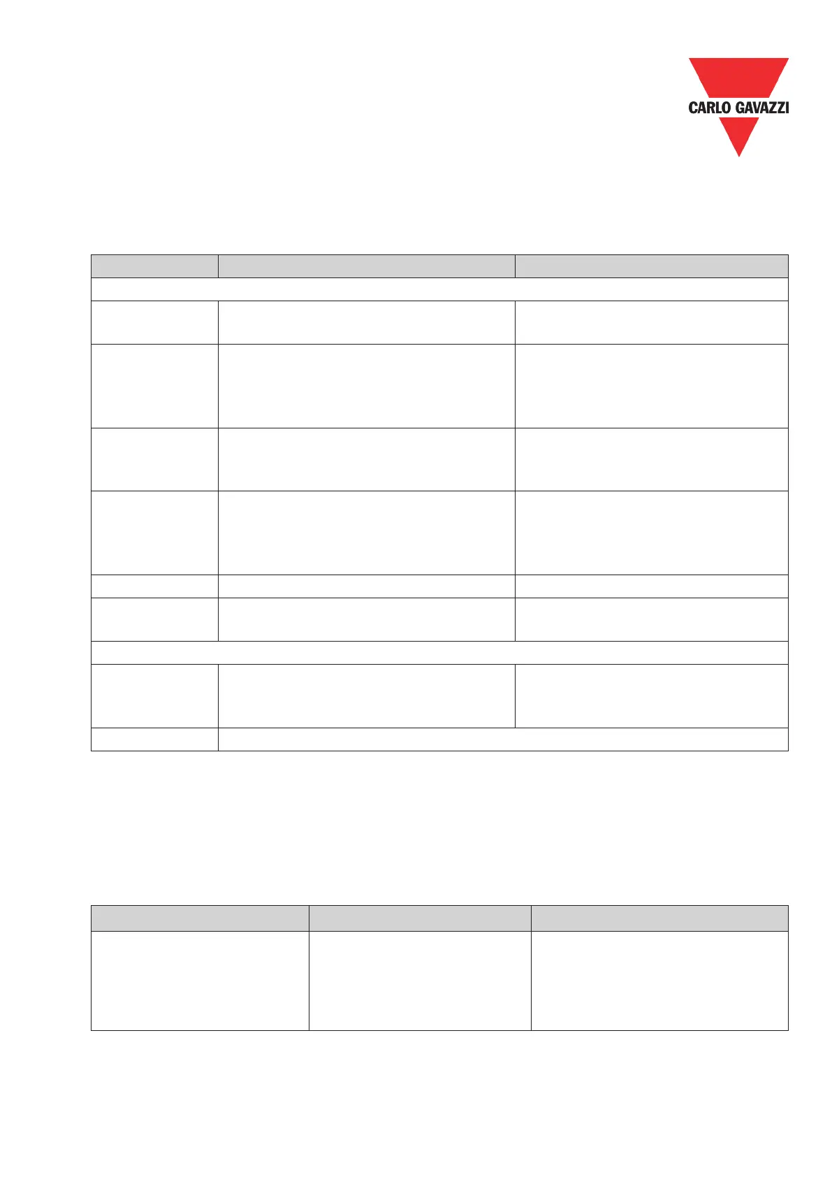
5.1. LED Display
5.2. Bus Diagnostic Data
POW LED and BUS LED are used to monitor the RV-PDP communication status.
RV-PDP provides 8 bytes diagnostic data when the abnormal communication occurs or
parameter “LossSPComTreat” is set to report alarm.
It includes 6 bytes standard diagnostic data and 2 bytes device related diagnostic data. The
following table shows the meanings of the 8 bytes:
Byte 7 indicates the length of device related diagnostic data, including itself, so byte 7 is
always 2. Byte 8 indicates the SP communication status when the error occurs.
If there is a communication error detected between RV-PDP unit and drive base unit (RVLF),
the error code will be displayed on the digital keypad of drive.
LED state Description Corrective Actions
POWER LED
OFF No power
Verify the power supply of RV-PDP
unit.
Orange SPComm not establish
1, Check the connection between
the RV-PDP unit and base unit 2,
Check the communication setting in
base unit is (19200, 8, N, 1)
Flashing
Red LED
SPComm error occur
Check the PLC program, and en-
sure the communication address
in RV-PDP unit is correct.
Rapid Flashing
Red LED
Invalid PROFIBUS address set via
switch
Check whether the switch value is
valid, valid value of slave is within
1~125. Set the valid value and re-
power.
Green ON Power supply present
Green ash
Communication with the base unit
correct.
BUS LED
OFF
OFF DPComm not establish
1, Verify network installation is OK
2, Check the user parameter assi-
gnment of RV-PDP unit is correct
Green on DPComm is established
Bytes 1~6 Byte 7 Byte 8
Standard diagnostic data Length in bytes 2
SPComm status
00 - normal
01 - SPComm return error code
02 - SPComm time out
 Loading...