each field is highlighted, the truncated24-character descriptor
is displayed on the message line. Use the INC/DEC buttons or
the MODIFY rotary knob to adjust the highlighted vldue. If the
EXIT button is pressed, the System Pilot will return to the
Program screen or the Table List screen.
SETUP- Selecting the SETUP option from the System
Pilot's Progrlun screen allows the user to access a special time
saving feature for Universal Controller configuration. This
feature helps expedite the configuration process by presenting
a controller-specific menu that guides the user through the
controller's setup procedure.
NOTE: This option only applies when the System Pilot is in
communication with a Universld Controllel:
DETACH- Select this option from the Program screen to
disconnect fi_)m the device to which the System Pilot is
cmrently attached. When plugged in locally to the Zone
Controller. the System Pilot will attach to itself and display the
System Pilot default screen.
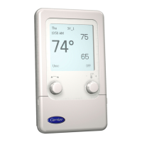
Modifying Set Points--The VVT® zone controller
default screen displays two set points. The Remote Attach
Default scleen will display up to two set points. The user can
modify the displayed set points by turning the MODIFY rotary
knob or pressing the INC/DEC buttons. The displayed set
points will blink.
The System Pilot will modify a set point subject to the
limits read from the controllel: If thele are two set points, the
System Pilot will modify them simultaneously and will
preserve the diffelence between them subject to the limits read
from the controllel:
The System Pilot hits configurable high and low limits for
set points, as defined in the System Pilot Configuration Table
and the System Pilot remote attach configuration table. On a
Remote Attach Default screen, the limits will be applicable to
the set points if the set point units are degrees, otherwise, they
will be ignored.
The System Pilot's internal limits will not affect the display.
The System Pilot reads the set points from the device and
displays them its read, even if they are outside the configured
System Pilot limits.
Pressing SELECT while a set point is blinking sends the new
set point to the controllel: Before sending the new set point to
the device, the System Pilot will clamp the set point to its own
internld limits. The System Pilot will also adjust the value on the
screen to match the value sent to the device, if necessmy and
will display the clmnped set point on the screen. If clmnping a
set point results in a vldue that is outside the limits read IYomthe
device, the System Pilot will display an error indication ("LIM-
IT') and will not write the set point to the device.
Pressing EXIT while a set point is blinking will cause the
System Pilot to revert to the original set point. Changing the set
point without pressing SELECT or EXIT for 15 seconds will
07:00 08:00 0111 1000
08:00 17:000111 1100
09:00 15:00 10000011
00:00 00:00 00000000
00:00 00:00 00000000
00:00 00:00 00000000
00:00 00:00 00000000
00:00 00:00 00000000
messages >
Fig. 19 -- Time Schedule Screen
idso cause the System Pilot to write the new set point to the
controllel:
The System Pilot will not write set points to the controller
unless they have been changed IYomtheir original values.
Occupancy Override- To initiate an override from
the Zone Controller Default Screen (if the Zone Controller's
occupancy status is UNOC), press the SELECT button for less
than 3 seconds. The occupancy status will begin to blink.
While the occupancy status is blinking, use the INC/DEC
buttons or the MODIFY rotm'y knob to adjust the occupancy
status. If the occupancy status is changed to OCC and then
SELECT is pressed, the System Pilot sends the occupancy
ovenide to the Zone Controllel:
If the occupancy status has been changed and the user does
not press SELECT or EXIT within 15 seconds, the System
Pilot will send the occupancy override to the controller and the
occupancy status will stop blinking. If the occupancy status has
not been changed, the System Pilot will not send occupancy
status.
If the user presses EXIT while the occupancy status
is blinking, the System Pilot will revert to the UNOC status.
The System Pilot will not write change the Zone Controller's
occupancy status.
If communication to the Zone Controller fails, the System
Pilot will display "COMFAIU' on the bottom line for 5 seconds.
NOTE: An occupancy override from the System Pilot will be
summed into the Tenant Billing Option's accumulation of
override times.
Alternate Maintenance Table -- To display the Sys-
tem Pilot Alternate Maintenance Table (ALT_DISP), pless the
SELECT button for at least 3 seconds from the Zone Controller
Default Screen. The System Pilot will display the Linkage
Controller or zone controller Alternate Maintenance Ntble
shown in Fig. 20, depending on whether or not the attached Zone
Controller is has been designated as a Linkage Coordinator
tin the Zone Controller's Linkage Configuration [LINKAGEI
Table).
If the Zone Controller is not a Linkage Coordinatol: the
ALT DISP table will simply display the zone controller's
Points Display Table (POINTS) values. If the Zone Controller
is itLinkage Coordinatol: the ALT DISP table will display the
zone controller's Points Display Table values followed by the
Master Zone Maintenance Table (MZNMAINT) vldues.
NOTE: The user will not be able to force any values from this
table regmdless of whether the same point is forcible from any
other table.
Use the SCROLL UP/DOWN, NAVIGATE, or PAGE UP/
PAGE DOWN buttons to scroll through the table. Pressing the
EXIT button causes the System Pilot to return to the Zone
Controller Default screen.
Bus Scan -- If the PAGE UP and PAGE DOWN buttons
iue pressed at the same time for 3 seconds and if the attached
device is a Linkage Coordinatol: then the System Pilot will
dispkiy the Bus Scan screen. See Fig. 21.
NOTE: If the attached device is not a Linkage Coordinatol: the
System Pilot will ignore this button combination.
Approximately every sixty seconds, the Linkage Coordinator
attempts to communicate with its associated Zone Controllers,
optional Bypass Controllel: and optional Air Source. The status
of this communication attempt is shown in the Bus Scan screen.
The top line shows the title "3V Bus Scan: NNN," where
NNN is the bus number of the attached device. The next line is
the &tta header, which is shaded gray. The rest of the screen
shows the following data from the scanned devices: device
address (Addr), device type (DevType), allum flag CAlm) and
status (Stat).
11
 Loading...
