MAINTENANCE TABLE
System Pilot Maintenance Table (PILOT-
MNT) -- The System Pilot Maintenance Table is shown in
Table 9, The maintenance values displayed in this table are
read-only values or points that can be written to (fomed).
Points that are fomeable will be indicated,
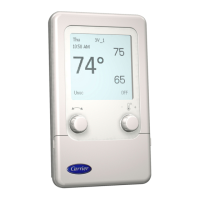
SYSTEM PILOT STATUS SPACE TEMPERATURE- This
point displays the space temperature from a thermistor located
in the System Pilot.
Space
Temperature: Valid Display -40.0 to 245.0 F
Fomible? Yes
SYSTEM PILOT STATUS OUTSIDE AIR TEMPERA-
TURE -- This point displays the outside air temperature.
Outside Air
Temperature: Valid Display -40.0 to 245.0 F
Fomible? Yes
COMMUNICATION MODE -- This point displays whether
the System Pilot is on the Career communicating network bus
or on a local bus wired to a VVT® zone controller's COMM2
port.
If Communication Mode is Local, then the System Pilot is
attached to itself or to the VVT zone controller on the same
local bus. If Communication Mode is set to CCN, then
the System Pilot is attached to itself or to another CmTier
communicating device on the network.
Communication
Mode: Valid Display Local / CCN
Fomible? No
ALARMS IN ALARM HISTORY -- This point displays the
number of alarms currently stored in the alarm history table.
Alarms in
Alarm History: Valid Display 0 to 5
Fomible? No
CLEAR ALARM HISTORY -- Forcing this decision to Yes
clears all alarras in the Alarm Histo U Table and sets this
decision set back to No.
Clear Almm
Histoly: Valid Display No / Yes
Forcible? Yes
REMOTE ATTACH BUS NUMBER -- This point displays
the bus number of the Remote Device that is configured in the
Remote Attach Configuration Table. The remote device can be
on any Carrier network bus.
Remote Attach
Bus Number: Allowable Entries 0 to 239
Forcible? No
REMOTE ATFACH ELEMENT NUMBER --This point dis-
plays the element number of the Remote Device that is
configured in the Remote Attach Configuration Table.
Remote Attach
Element Number: Valid Display 0 to 239
Forcible? No
REMOTE ATTACH STATUS-- Tiffs point displays the
communication status of the Remote Device. This status will
be up&tted eveU 15 seconds.
• Disabled = Remote Attach Enable is Disabled
• Active = Remote Attach Enable is Enabled, SPT is
being updated successfully in the remote device
• Commfail = Remote Attach Enable is Enabled but
communication to the remote device has tidied
Remote Attach
Status: Valid Display Disabled, Active,
Commfail
Forcible? No
ATTACHED DEVICE BUS NUMBER-- This point dis-
plays the bus number of the attached device.
Attached Device
Bus Number: VtflidDisplay 0 to 239
Forcible? No
ATTACHED DEVICE ELEMENT NUMBER -- This point
displays the element number of the attached device.
Attached Device
Element Number: Valid Display 0 to 239
Forcible? No
ATTACHED DEVICE NAME -- This point displays the
name of the attached device.
Attached
Device Name: Valid Display Up to 8 chmacteLs - up-
per case letters, numbers,
-, or
Forcible? No
Table 9 -- System Pilot Maintenance (PILOTMNT)
DESCRIPTION DISPLAY
System Pilot Status
Space Temperature xxx,x °F
Outside Air Temp xxx,x °F
Communication Mode Local/CCN
Alarms in Alarm History x
Clear Alarm History No/Yes
Remote Attach
Bus Number xxx
Element Number xxx
Status XXXXXXXX
Attached Device
Bus Number xxx
Element Number xxx
Device Name XXXXXXXX
NOTES:
1. Defaults are the System Pilot element number and bus number.
2. Remote Attach Status text: "Disabled", "Active", or "Commfail."
POINT DEFAULT
SPT
OAT
COMMODE
NUM_ALRM
CLR ALRM
RABUSNO
RAELENO
RASTATUS
ATBUSNO
ATELENO
ATDEVNAM
RANGE
-40-245
-40-245
Yes/No
-40
-40
Local
0
No
o
o
Disabled
(See Note 1)
(See Note 1)
SYSPILOT
18