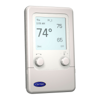
Timeout Feature -- If no user input is received for an
hour (i.e., if no buttons are pressed and no rotary knobs are
turned), the System Pilot reverts to file Default screen for its
default device. If connected to another device, the System Pilot
will re-attach to the default device.
Program Mode -- To enter Program mode and display
the Progrmn screen, press the SCROLL UP and SCROLL
DOWN buttons together for 3 seconds from the default screen.
The System Pilot will display one of the four program screens
shown in Fig. 12, depending on the security level that is speci-
fied in the System Pilot (PILOTCON) screen.
Use the SCROLL UP/SCROLL DOWN buttons or the
NAVIGATE knob to step through the options on the Program
screen. A description of the highlighted option will appem in
the bottom line of the screen and will indicate if the option is
not available. Press the SELECT button to select the cunentfy
highlighted option.
The following prograln screen options are available:
• ATTACH
• Ctlr-ID
• ALARM HIST
• TIME/DATE
• CONFIG
• MAINT
• SERVICE
• SETPOINTS
• SCHEDULES
• STATUS
• SETUP
• DETACH
ATTACH -- Selecting the ATTACH option fiom the Program
screen displays one of the Attach screens shown in Fig. 13 and
14, according to whether the System Pilot is on the CmTier
communicating network or on the local bus.
The center portion of the screen shows the 8-character
controller name, bus number and element number for the
devices to which the System Pilot can attach. The first entry in
the list always displays the default device and shows "Default"
instead of the actual controller name.
The user can use the SCROLL UP/DOWN, NAVIGATE, or
PAGE UP/PAGE DOWN buttons to scroll through the list of
devices. To modify tin existing bus and element number field,
press SELECT. then use INC/DEC or MODIFY to modify the
field, fllen press SELECT again to attach.
If the System Pilot is aheady attached to the specified ad-
dress, the System Pilot will display the message "Reattach?"
followed by three soflkeys displaying YES, NO, and ESC. Use
the NAVIGATE rottuy knob to move between the softkeys and
press SELECT. The user can also press EXIT to erase the
prompt and remain in the Attach screen.
If the System Pilot attaches to tm un-addiessed VVT®
Zone Controller (connected to the local COMM2 port), it will
display the Zone Controller's Cth-ID screen as a prompt for the
user to set the Zone Controller's address. This screen will show
the controller element number as 0, even though the controller
will actually be at its default element number of 140. Use the
instructions in the Cth-ID section below to set the addiess
before exiting from this screen. When the System Pilot attaches
to an addiessed Zone Controller. the System Pilot will bring up
the stan&ud Zone Controller Default screen.
CTLR-ID- Selecting the Cth-ID option from the Program
screen displays the Controller ID screen shown in Fig. 15.
The center portion of the screen shows the following
information for the controller to which the System Pilot is
cunently attached. The controller name, device description,
soflwaie p_ut number, reference number, element number, bus
number and baud rote are shown. The device description and
refeience number will be truncated, if necessary, to fit on the
screen. The controller name, device description, addiess and
baud rate are modifiable.
Level 1
<Controller Name>
SETUP
CONFIG SETPOINTS
SERVICE SCHEDULES
STATUS MAINT
TIME/DATE ALARM HIST
ATTACH DETACH
<Text & Error messages>
Level 3
<Controller Name>
Level 2
<Controller Name>
CONFIG
SCHEDULES
TIME/DATE
ALARM HIST
ATTACH
DETACH
<Text & Error messages>
Level 4
<Controller Name>
TIME/DATE
ALARM HIST
ATTACH
DETACH
<Text & Error messages>
TIME/DATE
ATTACH
DETACH
<Text & Error messages>
Fig. 12 -- Program Screens
 Loading...
