Heat Set Point Table Name -- Use this decision to specify the
Table Name containing the Heat Set Point to be monitored and/
or updated by the System Pilot.
Heat Set Point
Table Nmne: Allowable Entries Up to 8 characters - up-
per case letters, numbers,
-, or
Default Value (blank)
Heat Set Point Name -- Use this decision to specify the point
name of the Heat Set Point to be monitored and/or updated by
the System Pilot.
Heat Set Point
Name:
Allowable Entries Up to 8 chalacters - up-
per case letters, numbers,
-, or
Default Value (blank)
Heat Set Point Low Limit -- Use this decision to specify the
lowest value that can be sent to the heat set point specified by
the Table Name and Set Point Name. If the value being sent is
below this limit, the System Pilot will clmnp the value to this
limit before sending it to the device.
This limit will not affect the set point display. The System
Pilot will lead the set point fi'om the device and display it as
read, even if outside the high and low limits. Also, this limit
will only apply if the set point units are degrees F or C.
If clamping the set point results in a vtdue that is outside the
configuration limits read fiom the device, the System Pilot will
display an error indication ("LIMIT") and will not write the set
point to the device.
Heat Set Point
Low Limit: Allowable Entries -40 to 245 F
Default Value -40 F
Heat Set Point High Limit -- Use this decision to specify the
highest value that can be sent to the heat set point specified by
the Table Name and Set Point Name. If the value being sent is
above this limit, the System Pilot will clmnp the value to this
limit before sending it to the device.
This limit will not affect the set point display. The System
Pilot will read the set point fiom the device and display it as
read, even if outside the high and low limits. Also, flris limit
will only apply if the set point units are degrees F or C.
If clamping the set point results in a value that is outside the
configuration limits read fiom the device, the System Pilot will
display an error indication ("LIMIT") and will not write the set
point to the device.
Heat Set Point
High Limit: Allowable Entries -40 to 245 F
Default Value 245 F
Mode Calculation -- Use this decision to enable Mode Calcu-
lation. If Mode Calculation is enabled, the System Pilot will
read file configured Supply Temp Variable and Fan Status
Variable trod compute an operating mode for this specified
device while it is displaying the Remote Attach Default Screen.
Mode Calculation: Allowable Entries Enable / Disable
Default Value Disable
Supply Temp Variable -- Use this decision to specify the
name of the supply air temperature variable to be used in the
computation of the operating mode for this specified device.
This variable will be read from the device once per minute.
Supply Temp
Variable: Allowable Entries Up to 8 characters - up-
per case lettel_, numbers,
-, or _
Default Value SAT
Fan Status Variable -- Use this decision to specify the name
of the fan status variable to be used in the computation of the
operating mode for this specified device. This variable will be
read fi_m the device once per minute.
Fan Status
Variable: Allowable Entries Up to 8 characters - up-
per case lettel_, numbers,
-, or _
Default Value SFS
System Pilot Configuration (PILOTCON) Table --
The System Pilot Configuration Table is shown in Table 7. An
explanation of each configuration decision follows.
COMMUNICATION MODE -- Use this decision to indicate
whether the System Pilot is on the Carrier communicating
netwoN bus or on a local bus wired to a VVT® zone control-
ler's COMM2 port.
If Communication Mode is Local, then the System Pilot can
only attach to itself or to the VVT zone controller on the same
locM bus. If Communication Mode is Cmrier communicating
network (CCN), then the System Pilot can attach to itself or to
tiny other Cturier netwoN device on the network.
Communication
Mode: Allowable Entries Ix_cal / CCN
Default Value Ix_cal
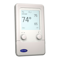
BACKLIGHT ALWAYS ON -- Use this decision to specify
whether the backlight should remain on or turn off during
inactive periods. If this decision is set to No, then the backlight
will be turned off if no buttons are pressed for 30 seconds.
Backlight
Always On: Allowable Entries No / Yes
Default Value No
Table 7 -- System Pilot Configuration (PILOTCON)
DESCRIPTION
Communication Mode
Backlight Always On
Display Units
English Language
SPT Sensor Trim
Show Name on Default
Default Dev: CCN Mode
Bus Number
Element Number
Write SPT to Default
Zone Setpoint Limits
Cool Setpt Low Limit
Cool Setpt Hi Limit
Heat Setpt Low Limit
Heat Setpt Hi Limit
Security Level
1=Full Access
2=Time, Set, Occ, Hot
3=Time & Setpoint
4=Read Only
DISPLAY
Local/CNN
No/Yes
US/Metric
No/Yes
xx.x AF
No/Yes
xxx
xxx
No/Yes
POINT
COMMODE
LIGHTON
DSPUNITS
ENGLISH
SPT TRIM
SHO-WNAME
DEFBUSNO
DEFELENO
DEFWRITE
RANGE
0-1
0-1
0-1
0-1
-9.9-9.9
0-1
0-239
0-239
0-1
xx.x dF
xx.x dF
xx.x dF
xx.x dF
x
C_LO LIM
C_HI -LIM
H_LO LIM
H_HI -LIM
SECURITY
50-99
50-99
50-99
50-99
1-4
DEFAULT
Local
No
US
Yes
0.0
No
0
0
No
68
78
65
75
1
15