OPERATION
Power-Up Display- When the System Pilot is powered
up, it attaches (initiates communication) to a device that has
been designated as the System Pilot's default device. The
System Pilot then displays that device's custom Default screen,
if such a screen exists. [f the System Pilot attaches to an
extermfl device that does not have a custom Default screen, the
System Pilot roads that device's first status table and displays it
as the Default screen.
DEFAULT DEVICE DESIGNATION -- If the System Pilot
is connected to a local bus of a VVT® Zone Controller
(Comm2), the default device is the local zone controllel: If the
System Pilot is on the Carrier communication bus, and a 3V TM
zone is the default device, then the device is user-selectable
from the PILOTCON Table screen.
If the System Pilot is not connected to a local or CmTier bus
device and no default device has been configured, the default
device is the System Pilot itself. The default device can also be
a device that has been designated as the remote attach device
(from the REMOTE Table). A remote attach device is a
designated CmTier network device to which the System Pilot
may write space temperature, compute an operating mode fol:
and monitor and modify set points.
All custom Default screens display the day of week, time,
and space or duct temperature. Other contents will vary accord-
ing to the attached device type. Examples of Default screens
for the System Pilot, VVT Zone Controllel: and Bypass
Controller me shown in Fig. 7-9.
OAT Display -- The System Pilot has an outside air tem-
perature (OAT) software point that can be fomed from the
Canier communicating network. If the System Pilot is display-
ing any default screen and the EXIT and SELECT buttons am
pressed together for one second, the System Pilot replaces the
default screen with a special screen that shows the OAT
vmiable value. An exmnple of the OAT Display screen is
shown in Fig. 10. When the System Pilot is connected to the
Zone Controller's local bus (Comm2), the OAT display feature
is disabled.
Mon SYSPILOT
8:49 AM
67 °
Fig. 7 -- System Pilot Default Screen
Mon CTRL1
8:49 AM
76
67° 62
Occ Fan
Fig. 8 -- Zone Controller Default Screen
Mon CTRL1
8:49 AM
56
7 1.2
Fan
Fig. 9 -- Bypass Controller Default Screen
Mon OAT
8:49 AM
82°
Fig. 10 -- OAT Display Screen
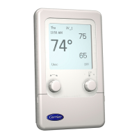
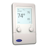
User Interface -- The System Pilot contains six buttons
and two rotary knobs with buttons, which allow the user to
navigate through the menus, select the desired options, and
modify data. See Fig. 11.
SCROLL UP/SCROLL DOWN --If displaying a table or a
list of items, these buttons move the cursor to the next line or
previous line in the table or list.
If the System Pilot is displaying a controller Default screen
and the SCROLL UP and SCROLL DOWN buttons am
pressed together for 3 seconds, the System Pilot changes to
Program mode.
The current security level can be overridden and full
program mode capability can be obtained by using the follow-
ing button sequence while a Default screen is displayed. Press
the SCROLL DOWN mad PAGE UP buttons together for 1
second, followed by the SCROLL UP and SCROLL DOWN
buttons pressed together for 3 seconds. The button pushes in
the sequence must be sepm'ated by no morn than one second.
The override into full program mode is a one-time override.
Pressing the SCROLL UP button along with the INC/DEC
button increases or decreases the contrast on the System Pilot
LCD display screen.
PAGE UP/PAGE DOWN --In screens that have more than 7
data lines (Ex: a Table List screen with more than 7 tables, or a
table with more than 7 decisions), these buttons replace the
items currently on the screen with the previous or next 7 items
from the table or list.
If there is additional data at the end or beginning of a table
or list that is not on the screen, the cursor will not advance
move down past the next-to-last line or up past the second line
on the screen.
 Loading...
