33
TROUBLESHOOTING CONTINUED
43 Communication failure with Unit A ● ● ●
44 Communication failure with Unit B ● ●
45 Communication failure with Unit C ○ ○ ●
46 Communication failure with Unit D ● ○ ●
47 Unit A freeze protection ○ ●
48 Unit B freeze protection ○ ● ●
49 Unit C freeze protection ● ● ●
50 Unit D freeze protection ● ●
51 Unit A overheating prevention protection ○ ●
52 Unit B overheating prevention protection ● ●
53 Unit C overheating prevention protection ●
54 Unit D overheating prevention protection ○ ○ ○
55 Unit A communication wire misconnection or expansion valve malfunction ● ○ ○
56 Unit B communication wire misconnection or expansion valve malfunction ○ ○
57 Unit C communication wire misconnection or expansion valve malfunction ○ ● ○
58 Unit D communication wire misconnection or expansion valve malfunction ● ● ○
Malfunction Checking and Elimination
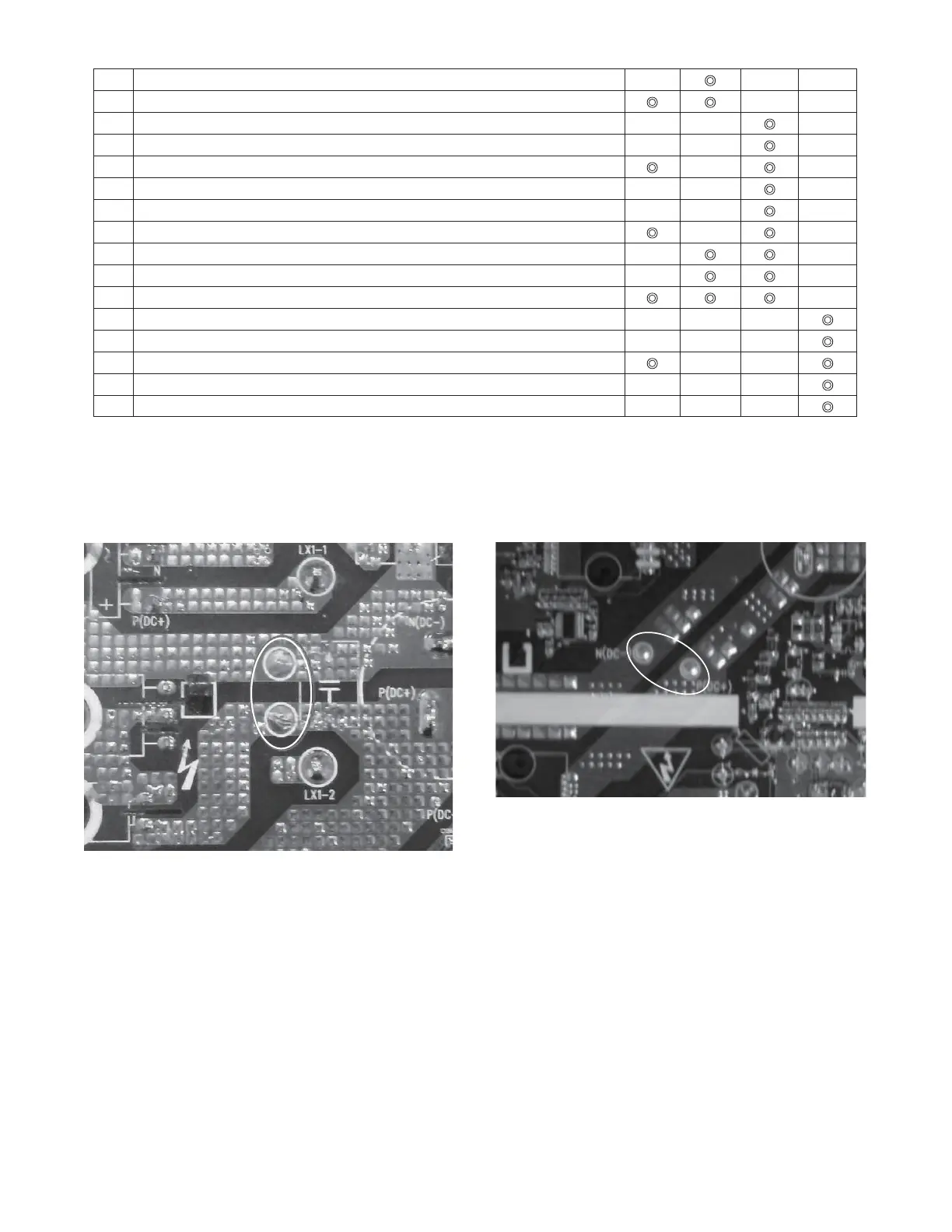
NOTE: Discharge power capacities at positions shown below. Voltage should be less than 20v (measured with a meter) prior to initiating
service work.
18k
24/30k
(1) IPM protection malfunction:
Main checking point:
S Is the input voltage of the unit within the acceptable range?
S Is the compressor connected correctly?
S Is the compressor winding resistance correct?
S Are the heat exchangers clean / unblocked?
S Is the refrigerant charge correct?
Flow chart:
 Loading...