83
APPENDIX A — CONTROLS OPERATION (CONT)
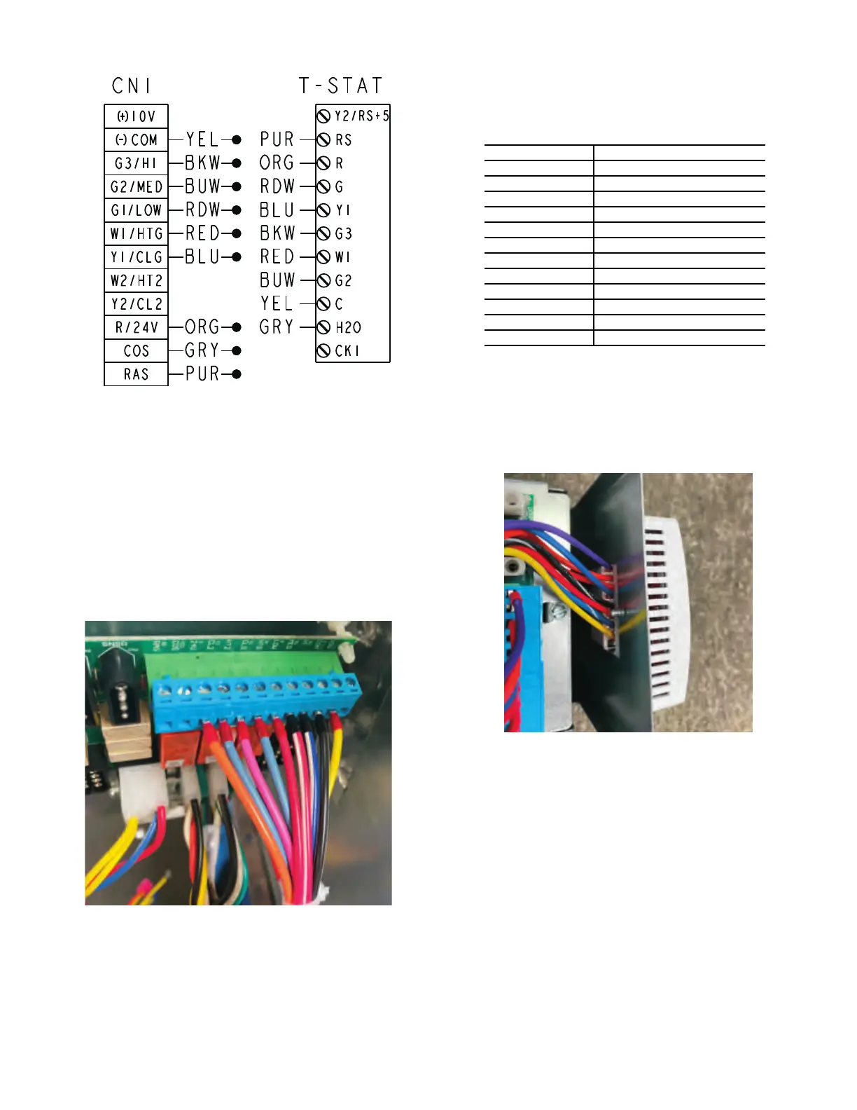
Fig. B — Factory Installed 24V Thermostat Wiring Diagram
Board Functions and Diagnostics
CN1 - 24V CUSTOMER INPUT (THERMOSTAT)
Use proper wire gauge and insulation type based on application
and local code requirements.
For detailed Carrier 24V thermostat control wiring diagrams, ref-
erence thermostat Installation Instructions. Refer to Table A and
Fig. A-B.
Fig. C — Thermostat Wire Harness Connection
Fig. D — Mounted Thermostat Connection
Table A — 3A-Speed ECM or PSC
CONNNECTION FUNCTION/DESCRIPTION
(+) 10V Not Used
(-) COM Ground Control Power
G3/HI Fan High Speed
G2/MED Fan Medium Speed
G1/LOW Fan Low Speed
W1/HTG Heat
Y1/CLG Cool
W2/HT2 Heat Stage 2
Y2/CL2 Cool Stage 2
R/24V 24V Controller Power
COS Changeover Sensor
RAS Room Air Sensor
NOTE: Does not apply to proportional or line voltage thermostat controls. The diagram represents a factory installed 24-v thermostat.
NOTE: Figure depicts a unit-mounted thermostat.

 Loading...


