84
APPENDIX A — CONTROLS OPERATION (CONT)
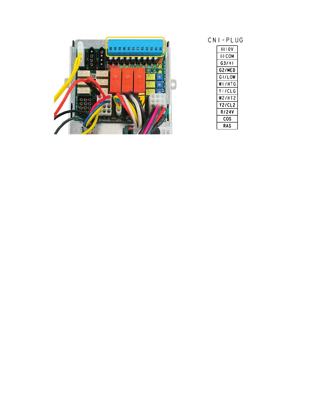
Fig. E — Thermostat Control Board (By Others or Remote Mounted)
For Thermostat Control By Others or Remote
Mounted Thermostat
Unplug blue connector from control board. Make appropriate
thermostat wiring connections and plug connector back to control
board. See Fig.
C-E.
CN2 - CHANGEOVER/RETURN AIR SENSOR
1. Power connector for 24V or Common-powered sensors
a. 24V powered sensors:
Applicable for Carrier-supplied air sensor, Programma-
ble, Non-programmable 24V Carrier thermostats.
b. Common-powered sensors:
Applicable for thermostats by others.
2. Sensor/switch:
a. 10k Thermistor
b. Bimetal Switch
CN3 - REMOTE SHUTDOWN INPUT
1. Provides dry contact for signal to BAS system – I/O:
a. Dry Normally Open
b. Wet Normally Open
c. Discrete Coil
2. When contact activated:
a. Motor OFF
b. Actuator OFF
c. Electric Heat OFF
d. Power to controller remains ON
3. BAS LED indicates when BAS relay circuit activated
CN4 - CONDENSATE OVERFLOW SWITCH
1. Low voltage condensate switch shuts down the unit when the
water level in the drain pan reaches an unsafe level.
a. Switch is normally closed and opens on an increase in
water level.
2. When contact activated, then:
a. Motor OFF
b. Valve Actuator OFF
c. Electric Heat OFF
d. Power to controller remains ON
3. OVF LED indication when condensate switch is activated.
CN5 - 2-STAGE COOLING/HEATING
1. Available with two stage coil for part load.
2. 24V On/Off, 24V Floating, 0-10V Proportional control
3. CL2 or HT2 LED indication when either 2-stage cooling or
heating activated
CN6 - 1ST STAGE COOLING/HEATING
1. 24V On/Off, 24V Floating, 0-10V Proportional control, Line
voltage
2. Contact factory for applications.
3. CLG or HTG LED indication when either first stage cooling
or heating activated
CN7 - CLASS II TRANSFORMER
1. 40VA, 75VA option
2. 24V LED activated when powered
CN8 - INCOMING POWER
CN9 - PSC MOTOR
1. 3-speed application
2. Either LOW/MED/HIGH activated when a speed is selected.
CN10 - EC MOTOR
1. 3-speed application
2. Solid State Switching
3. Either LOW/MED/HIGH activated when a speed is selected.
4. ECM LED indicates speed control is powered.
5. 0-10V LED intensity indicates increasing speed.

 Loading...


