85
APPENDIX A — CONTROLS OPERATION (CONT)
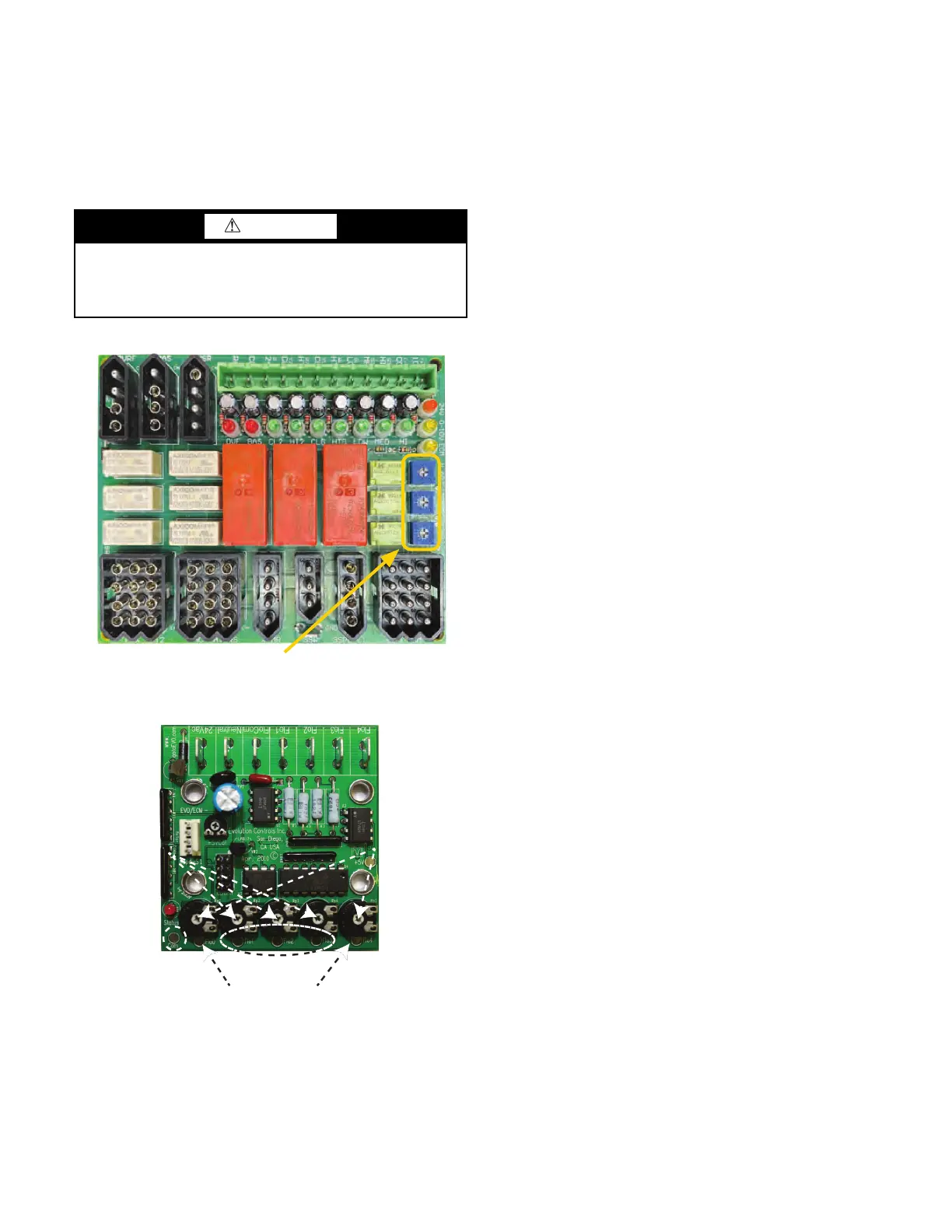
ECM Fan Speed Adjustment
If the unit is equipped with an ECM blower, additional steps may
be required during the air balancing process. Review project sub-
mittals or order acknowledgment to determine which ECM con-
trol scheme the unit has. Alternatively, match the control board to
the illustrations. See Fig. F-G.
Fig. F — 3-Speed, Potentiometer Adjustment
(ECM Only)
Fig. G — 4-Speed, Solid State with Potentiometer
NOTE: The unit has been factory configured to produce PSC
equivalent airflow on high speed, with medium and low speed set
at 80% and 60% of high, respectively. If these setting are accept
-
able, then no further configuring is required.
If alternative airflows are desired, use board mounted pots to ad-
just the airflow associated with each input.
To reset to initial factory settings, reference the voltages found on
the sticker next to the pots.
Each output can be adjusted from 0 to 100% of the motor's factory
programmed operating range. Use voltmeter and airflow chart (on
control box cover) to set values.
Adjusting the potentiometers requires the use of a Multi-meter
capable of measuring 0~5 vdc.
1. Only trained and qualified individuals should attempt to
adjust or service components on any electrical component.
Failure to follow safety rules could result in electrical shock
or hazard.
2. 24 VAC power must be supplied to ECM board to make
adjustments.
3. Set the electrical multimeter to Volts Direct Current (vdc) on
the 0~5 or 0~20 vdc scale.
4. Attach black (negative) lead of meter to the "Com" terminal
to the left of the potentiometers and below the Status light.
5. Attach the red (positive) lead of the meter to the terminal
below the Potentiometer needing adjustment.
a. High Speed: Using a small screwdriver, turn the H ADJ
potentiometer (CW for increasing speed, CCW for
decreasing speed).
b. Medium Speed: Using a small screwdriver, turn the
M ADJ potentiometer (CW for increasing speed, CCW
for decreasing speed).
c. Low Speed: Using a small screwdriver, turn the L ADJ
potentiomenter (CS for increasing speed, CCW for
decreasing speed).
VARIABLE AIRFLOW FOR 0-10 VDC
If a factory provided thermostat or DDC controller is utilized, then
the unit is already correctly configured.
Carrier recommends using the specified thermostat or DDC con-
troller to commission the unit whenever possible. However, the
blower can be started and operated without the thermostat. Con
-
sult factory for further instruction.
ECM VARIABLE AIRFLOW FOR 0-10 VDC
No control board is required and no field adjustments are possible.
Motor uses 0-10vdc signal directly. See control box label. Fan en
-
able at 1.5vdc.
GROUND TAB CONNECTION
1. For multimeter diagnostics.
CAUTION
Both of the procedures described below require the control
box to be powered while adjustments are made. Line voltage
components are concealed behind a secondary cover. How-
ever, installer should take all reasonable precautions.
Potentiometers
Flo 1, 2, and 3 Terminals
Flo 0 and 4 Terminals
Com
Pot Adjustment
Flo 1, 2, and 3
(in the Field)
Pot Adjustment
Flo 0 and 4
(Contact Factory)

 Loading...


