86
APPENDIX A — CONTROLS OPERATION (CONT)
LED Function and Outcomes
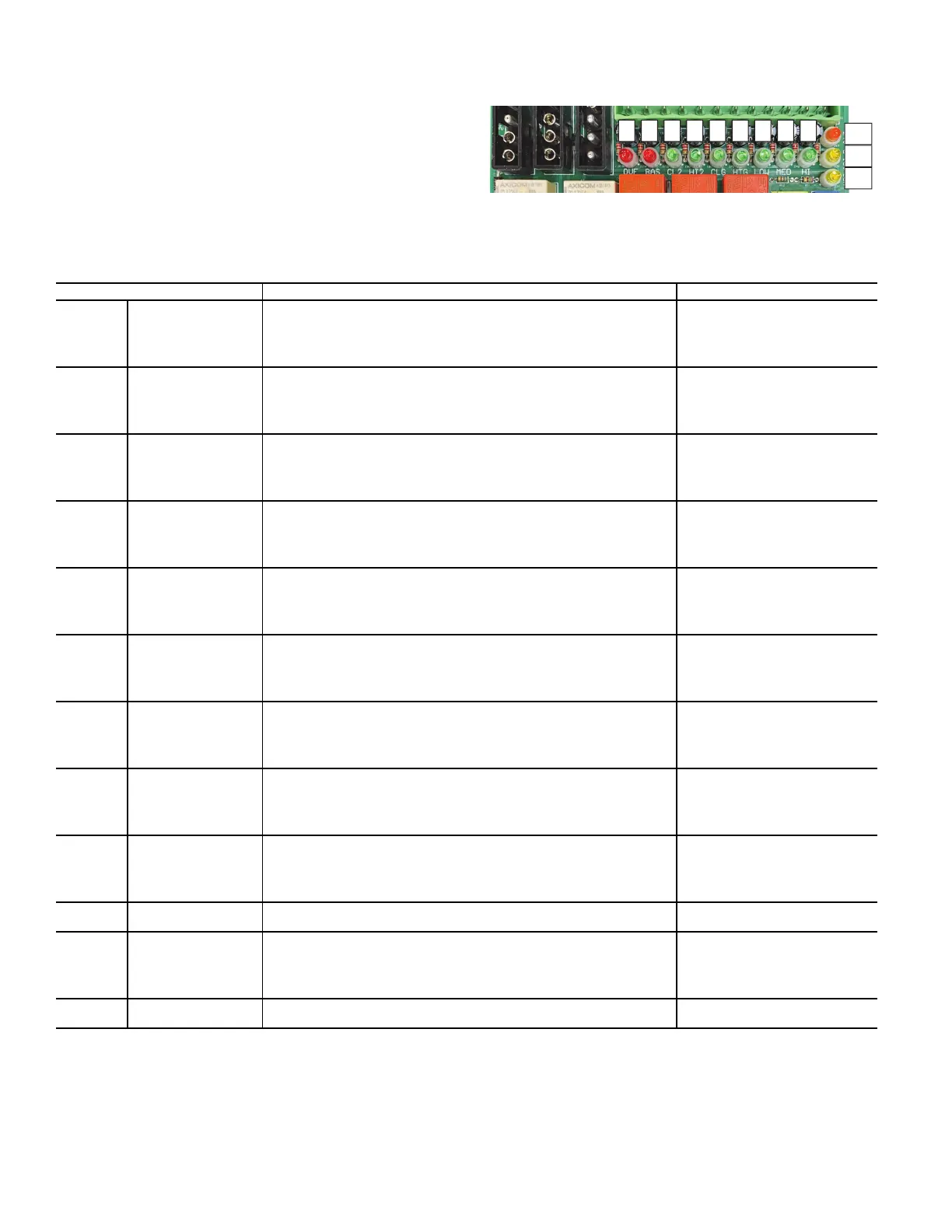
Refer to Table B and Fig. H for functions and commands.
Fig. H — LED Functions
Table B — LED Function and Outcomes (Sequence of Operation)
ITEM DESCRIPTION OUTCOME
A
Condensate Overflow
Switch (OVF)
Condensate switch is tripped by increasing water level in the drain pan.
OVF LED Shows Red
Motor OFF
Actuator OFF
Electric Heat Off
Power to controller remains ON
B
Remote Shutdown
Input (BAS)
24VAC externally applied to BAS CN3 or the internally-powered BAS CN3
loop is closed.
BAS LED shows RED
Motor OFF
Actuator OFF
Electric Heat Off
Power to controller remains ON
C
Cooling 2-Stage
(24VAC and 0-10VDC)
(CL2)
24VAC signal applied to CL2 of CN1.
2nd stage cooling relay (CL2) will actuate and supply 24VAC to Pin 9 of
connector CN5.
When 0-10VDC is applied to CL2, control signal will passively be present
at Pin 7 of the CN5 connector.
CL2 LED shows GREEN
Signal for 2nd stage cooling valve
present
D
0-Heating 2-Stage
(24VAC and 10VDC)
(HT2)
24VAC signal applied to HT2 of CN1.
2nd stage heating relay (HT2) will actuate and supply 24VAC to Pin 9 of
connector CN5.
When 0-10VDC is applied to HT2, control signal will passively be present
at Pin 7 of the CN5 connector.
HT2 LED shows GREEN
Signal for 2nd stage heating valve
present
E
Cooling 1st Stage
(24VAC and 0-10VDC)
(CLG)
24VAC signal applied to CLG of CN1.
1st stage cooling relay (CLG) will actuate and supply 24VAC to Pin 9 of
connector CN5.
When 0-10VDC is applied to CLG, that control signal will passively be
present at Pin 7 of the CN6 connector.
CLG LED shows GREEN
Signal for 1st stage cooling valve
present
F
0-Heating 1st Stage
(24VAC and 10VDC)
(HTG)
24VAC signal applied to HTG of CN1.
1st stage HTG relay will actuate and supply 24VAC to Pin 12 of connector
CN5.
When 0-10VDC is applied to HTG, that control signal will passively be
present at Pin 8 of the CN6 connector.
HTG LED shows GREEN
Signal for 1st stage cooling valve
present
G
Fan Low Speed
(24VAC)
(LOW)
24VAC signal applied to LOW of CN1.
The low speed PSC motor power relay and the low speed ECM signal
relays will be activated.
Line voltage will be present at Pin 2 of CN9 and the adjustable low speed
ECM DC signal will be present at Pin 5 of the CN10 connector.
LOW LED shows GREEN
Signal for low speed present
H
Fan Med Speed
(24VAC)
(MED)
24VAC signal applied to MED of CN1.
The medium speed PSC motor power relay and the medium speed ECM
signal relays will be activated.
Line voltage will be present at Pin 3 of CN9 and the adjustable medium
speed ECM DC signal will be present at Pin 5 of the CN10 connector.
MED LED shows GREEN
Signal for medium speed present
I
Fan High Speed
(24VAC) (HI)
24VAC signal applied to HI of CN1.
High speed PSC motor power relay and the high speed ECM signal relays
will be activated.
Line voltage will be present at Pin 4 of CN9 and the adjustable high speed
ECM DC signal will be present at Pin 5 of the CN10 connector..
HI LED shows GREEN
Signal for high speed present
J
24VAC Board Power
(24V)
24VAC signal supplied from internal transformer. 24VAC required for
board operation.
24V LED shows ORANGE
K
0-10V ECM Speed
Control (0-10V)
0-10V signal supplied to 10V of CN1.
Signal passively present at Pin or CN10 connector.
0-10 LED shows YELLOW
Intensity of the LED illumination will
vary depending on the amplitude of
the 0-10VDC signal (10VDC is
brightest)
L
Power Supply by ECM
(ECM)
ECM Motor connected to CN10 and powered by line voltage.
Signal from the ECM regulator is present at Pin 6 of the CN10 connector.
ECM LED shows YELLOW

 Loading...


