Do you have a question about the Carrier PrimeLINE and is the answer not in the manual?
General safety notices supplementing specific warnings and cautions for operation and maintenance.
Immediate action for any injury, emphasizing professional medical attention.
Safety measures during operation, including PPE and power disconnection.
Precautions during maintenance, emphasizing power off and safety devices.
Explanation of DANGER, WARNING, and CAUTION labels and their consequences.
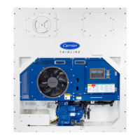
Overview of unit construction, power, controller, and refrigerant types.
Details on R-134a and R-513A refrigerants and conversion procedures.
How to identify unit configuration via model number and PID on the nameplate.
Description of unit features like control box, temp/pressure readouts, compressor, coils, EEV, fans, plates.
Overview of various factory or field-equipped options like battery, dehumidification, XtendFRESH.
Overview of the unit design, component accessibility, and nameplate location.
Description of the front section, component accessibility, and nameplate location.
Components included in the compressor section, such as DUV, pressure transducers, and sensors.
Components of the air-cooled condenser section, including fan, coil, receiver, and valves.
Description of the optional water-cooled condenser and its types.
Function of fresh air vents for commodity ventilation and Vent Position Sensor (VPS).
Description of the evaporator section, air circulation, and component accessibility.
Components within the control box, including breakers, contactors, transformer, and controller.
Function of the CIM as a slave module for monitoring station communication.
Overview of the Micro-Link 3 system components: controller, keypad, and display.
Overview of controller software functions: configuration and operational software.
General sequences for cooling, heating, and defrost operations based on inputs.
Independent function generating alarms for out-of-range parameters or incorrect signals.
Independent controller function for automatic testing of unit components.
Integrated software to eliminate temperature recorder and paper chart, accessed via keypad.
Checks for cleanliness, damage, and securing of components inside the unit.
Procedures for connecting 380/460 VAC and 190/230 VAC power sources.
Purpose of fresh air vents for ventilation and vent position sensor (VPS).
Connecting water-cooled condenser when cooling water is available.
Connecting remote monitor plug to energize remote circuits for lights.
Procedures for starting and stopping the unit, including safety warnings.
Checks performed after starting the unit, including physical inspection and function codes.
Independent controller function for automatic testing of unit components.
Checking temperature probe accuracy and disagreement during defrost or pre-trip.
Overview of optional operating modes for enhanced functionality.
Troubleshooting steps for units that fail to start or stop intermittently.
Troubleshooting for units running constantly in cooling mode.
Troubleshooting for units with insufficient cooling performance.
Troubleshooting for units that do not heat or have insufficient heating.
Troubleshooting for units failing to stop heating when required.
Troubleshooting steps for units that do not defrost correctly.
Diagnosing issues related to high or low discharge and suction pressures.
Troubleshooting abnormal noise or vibrations from the compressor or fans.
Troubleshooting issues related to microprocessor control, sensors, and wiring.
Diagnosing issues with evaporator air flow, including blocked coils or fan problems.
Troubleshooting XtendFRESH system, including vent opening and sensor calibration.
Troubleshooting EEV issues like low suction pressure or improper superheat.
Troubleshooting autotransformer issues related to unit start-up.
Troubleshooting WCC issues like high discharge pressure or fan start/stop.
Troubleshooting compressor operating in reverse and potential damage.
Diagnosing issues related to abnormal discharge temperatures.
Troubleshooting abnormal current readings.
Overview of service procedures covered in the section, see Table of Contents for topics.
Description of manifold gauge set usage for pressure, charge, and evacuation.
Description of double seat service valves and access valves for servicing.
Procedure to pump refrigerant into the high side for servicing components.
Procedures for finding and repairing refrigerant leaks using electronic detectors or soapsuds.
Procedures to remove moisture and contaminants from the refrigeration system.
Procedures for checking, adding, and verifying refrigerant charge.
Procedure for converting units to R-513A refrigerant, applicable to specific models.
Procedures for removing and replacing the compressor, including warnings and notices.
Service procedures for the high pressure switch.
Procedures for cleaning, removing, and installing the condenser coil.
Description of condenser fan operation and fan motor removal/replacement.
Procedures for cleaning and de-scaling the water-cooled condenser.
Checking for restricted or plugged filter drier, and moisture-indicator.
Regular cleaning of the evaporator coil and drain pan hoses.
Information on evaporator heaters, contactor wiring, and pre-trip detection.
Description of evaporator fan operation and fan motor replacement.
Cleaning evaporator section exposed to fumigants, identifying white powder.
Automatic device maintaining superheat, preventing liquid refrigerant entry.
Optional component for setting humidity set points and reducing moisture.
Coil view and procedures for removing and installing the ESV.
Automatic device for maintaining superheat, requiring periodic inspection.
Evaluating DUV or compressor seal failure by running pre-trip test P6-7.
Procedures for removing and installing the DUV.
Configurable code Cd41 for timed operation of automatic valves for troubleshooting.
Checking autotransformer for proper operation when unit does not start.
Guidelines for handling controller modules, including warnings and precautions.
Test points on the controller for troubleshooting electrical circuits.
Procedures for removing and installing the controller module.
Procedures for replacing standard and rechargeable batteries.
Procedures for data downloads, software loading, and configuration changes.
Service procedures for temperature sensors including ice bath prep and checkout.
Specific model number for which the declaration applies.
List of applied European Directives and Harmonized Standards for the equipment.
| Brand | Carrier |
|---|---|
| Model | PrimeLINE |
| Category | Industrial Equipment |
| Language | English |