T-362 3–10
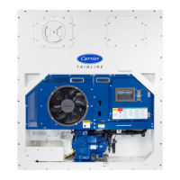
3.1.7 Control Box Section
The control box (see Figure 3.10) includes: the manual operation switches, circuit breaker (CB-1), compressor, fan
and heater contactors, control power transformer, fuses, keypad, display module, current sensor module, controller
module and the communications interface module.
Figure 3.10 Control Box Section
1) Compressor Contactor (CH)
2) Unit Phase A Contactor (PA)
3) Unit Phase B Contactor (PB)
4) Heater Contactor (HR)
5) Controller / DataCORDER Module
6) Remote Monitoring Receptacle (RM)
7) Start-Stop Switch (ST)
8) Controller Battery Pack (standard location)
9) Control Transformer (TS)
10) Evaporator Fan Contactor High Speed (EF)
11) Evaporator Fan Contactor Low Speed (ES)
12) Condenser Fan Contactor (CF)
13) Circuit Breaker 460V (CB1)
14) Current Sensor Module
- - - - -
3.1.8 Communications Interface Module
The unit may be equipped with an optional communications interface module, which is a slave module that allows
communication between the refrigeration unit and a ship system master central monitoring station. The module will
respond to communication and return information over the ship’s main power line. If equipped, this module is
located next to the Controller. See the master system technical manual for further information.
1
2
3
4
5
6
7
8
9
10
11
13
14
12
 Loading...