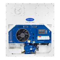
7–7 T-362
1. Connect the gauge manifold to the compressor discharge and suction service valves. For units operating on
a water-cooled condenser, change over to air-cooled operation.
2. Bring the container temperature to approximately 0°C (32°F) or below. Then set the controller setpoint to -
25°C (-13°F).
3. Partially block the condenser coil inlet air. If covering the lower portion of the coil is not sufficient, remove the
left hand infill panel and cover the left side of the coil. Increase the area blocked until the compressor
discharge pressure is raised to approximately 12.8 bar (185 psig).
4. On units equipped with a receiver, the level should be between the glasses. On units equipped with a
watercooled condenser, the level should be at the center of the glass. If the refrigerant level is not correct,
See Section 7.7.2 and Section 7.7.3 to add or remove refrigerant as required.
7.7.2 Adding Refrigerant to System - Full Charge
1. Evacuate unit and leave in deep vacuum. See Section 7.6.1.
2. Place refrigerant cylinder on scale and connect charging line from cylinder to liquid line valve. Purge
charging line at liquid line valve and then note weight of cylinder and refrigerant.
3. Open liquid valve on cylinder. Open liquid line valve halfway and allow liquid refrigerant to flow into the unit
until the correct weight of refrigerant has been added as indicated by scales. See Section 3.2
4. It may be necessary to finish charging unit through suction service valve in gas form, due to pressure rise in
high side of the system.
5. Backseat the manual liquid line valve to close off the gauge port. Close liquid valve on cylinder.
6. Start the unit in cooling mode. Run for approximately 10 minutes and check the refrigerant charge.
7.7.3 Adding Refrigerant to System - Partial Charge
1. Examine the refrigerant system for any evidence of leaks, repair as necessary. See Section 7.5.
2. Maintain the conditions outlined in Section 7.7.1.
3. Fully backseat the suction service valve and remove the service port cap.
4. Connect the charging line between suction service valve port and refrigerant cylinder. Open the VAPOR valve.
5. Partially frontseat (turn clockwise) the suction service valve and slowly add charge until the refrigerant
appears at the proper level. Be careful not to frontseat the suction valve fully. If the compressor is operated
in a vacuum, internal damage may result.
7.8 Converting to R-513A Refrigerant
This procedure only applies to R-513A-ready units for 69NT40-561-500 models. This conversion is only by
approval of the equipment owner.
1. The compressor will have a green dot on the DUV fitting to note that it can accept R-513A.
2. Recover all R-134a refrigerant from the unit, by following procedure in Section 7.6.
3. Change the filter drier.
4. Evacuate to 500 microns by placing the vacuum pump on the liquid line and suction service valve.
5. Charge the unit with a full charge of R-513A refrigerant, by following procedure in Section 7.7.2. Charge
amounts are found in Section 3.2 Refrigeration System Data.
When charging the unit with R-513A refrigerant, charge as a liquid only. R-513A is an azeotrope
blend containing R-1234yf and R-134a. Charging or topping off as a vapor will result in an
incorrect mixture of blend in the system.
6. Upon completion, change the refrigerant label (Carrier P/N 76-50235-00) on the front of the unit indicating
the change in refrigerant.
 Loading...