7–35 T-362
7.27.2 Controller Troubleshooting
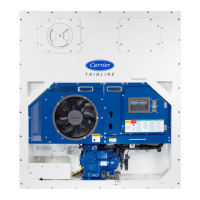
A group of test points (TP, see Figure 7.19) are provided on the controller for troubleshooting electrical circuits (see
schematic diagram sections). A description of the test points is provided in Table 7–2.
NOTE
Use a digital voltmeter to measure AC voltage between TP’s and ground (TP9), except for TP8.
Figure 7.19 Controller
1) Micro-Link 3 Controller /
DataCORDER Module
2) Mounting Screw
3) Connectors
4) Test Points
5) Fuses
6) Control Circuit Power Connection
7) Software Programming Port
8) Battery Pack (Standard Location)
- - - - -
Table 7–2 Test Point Descriptions
Test Point Description
TP1 Not used in this application.
TP2 Check if the high pressure switch (HPS) is open or closed.
TP3 Check if the water pressure switch (WP) contact is open or closed.
TP4
Check if the internal protector for the condenser fan motor (IP-CM) is open or closed.
TP5
Check if the internal protectors for the evaporator fan motors (IP-EM1 or IP-EM2) are
open or closed.
TP6 (if equipped) - Check if the controller liquid injection valve relay (TQ) is open or closed.
TP7 Check if the controller economizer solenoid valve relay (TS) is open or closed.
TP8 Not used in this application.
TP9 Chassis (unit frame) ground connection.
TP10 Check if the heat termination thermostat (HTT) contact is open or closed.
MA
CONTROLLER
Micro-Link3
With
DataCORDER
MB
MC
F2
(5A)
TP
F1
(5A)
F3A
(7.5A)
F3B
(7.5A)
KH
OC1
KA
EN12830
CARRIER
S/N: 0491162
TB C1
KE
REV 5147
YYWW:
KD
1035
KC
12-00579-00
59980
KB
1
2
3
4
5
3
6
3
8
7
3
 Loading...