T-362 Index–4
P6-5
4–45
P6-6 4–46
P6-7
4–46
P6-9
4–46
P7-0 4–46
P7-1
4–46
P8-0
4–47
P8-1
4–47
P8-2 4–47
P9-0 4–47
Painted Surfaces
7–53
Perishable Dehumidification
4–20
Perishable Dehumidification, Bulb Mode
4–21
Perishable Economy 4–21
Perishable Heating
4–20
Perishable Idle, Air Circulation
4–19
Perishable Mode Cooling, Sequence of Operation 4–22
Perishable Mode Heating, Sequence of Operation
4–23
Perishable Mode Temperature Control 4–19
Perishable Mode, Trim Heat
4–23
Perishable Pulldown
4–19
Perishable Steady State
4–19
Pharma Mode 4–18
Pharma Mode Operation
5–14
Physical Inspection
5–5
Plate Set 2–2
Power Cables and Plug Location
3–1
Pressure Readout 2–1
Pre-Trip Data Recording Description
4–55
Pre-Trip Diagnosis
5–6
Pre-Trip Diagnostics 4–42
Pre-Trip Test Codes
4–42
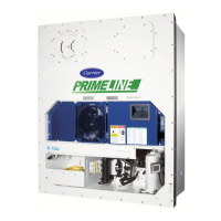
PrimeLINE 2–1
PrimeLINE models
2–1
Probe Diagnostics 5–7
Protection Modes of Operation
4–28
Pump Down
7–3
Push Button Switches 4–2
Q
QUEST Mode 4–13
QUEST Mode Operation
5–14
QUEST operation
4–28
QUEST Option
2–4
R
Receiver Liquid Level / Moisture Indicator Location 3–2
Receiver Location
3–2
Receiver Sight Glass Location 3–2
Refrigerant - Adding Full Charge to System
7–7
Refrigerant - Adding Partial Charge to System
7–7
Refrigerant - Checking Charge 7–6
Refrigerant Description
2–1
Refrigerant Leak Checking
7–4
Refrigeration Circuit Description 3–14
Refrigeration System Data
3–11
Remote Monitoring 2–2
Remote Monitoring Receptacle Location
3–1
Replacing the Evaporator Fan Assembly
7–23
Return Recorder Sensor (RRS) Location 3–7
Return Recorder Sensor (RRS) Service
7–51
Return Temperature Sensor (RTS) Location
3–7
Return Temperature Sensor (RTS) Service
7–51
S
Safety and Protective Devices 3–13
Safety Notices
1–1
Safety Summary 1–1
Sampling Type (dCF05 & dCF06)
4–51
Sensor
7–51
Sensor Checkout 7–40
Sensor Configuration (dCF02)
4–49
Service Access Valve Location 3–2
Service Connections
7–2
Specific Hazard Statements
1–1
Standard Battery
7–36
Standard Operation Description 3–14
Start Temperature Recorder
5–5
Start Up - Compressor Bump Start 4–19
Start Up - Compressor Phase Sequence
4–19
Starting and Stopping Instructions
5–5
Starting the Unit 5–5
Start-Stop Switch (ST) Location
3–1
Start-Up Inspection
5–5
Stopping the Unit 5–5
Suction Connection Location
3–2
Suction Pressure Transducer (SPT) Location
3–2
Suction Service Valve Location
3–2
Supply Recorder Sensor (SRS) Location 3–2
Supply Temperature Sensor (STS) Location 3–2
T
Temperature Control Microprocessor System 4–1
Temperature Readout
2–1
Temperature Sensor Service
7–40
Thermometer Port 2–3
TripWise Mode
4–17
TripWise Operation
5–9
TripWise Option 2–4, 5–9
Troubleshooting Flow Chart
6–1
Troubleshooting P6- 7 (DUV) 7–30
Troubleshooting, Abnormal Currents
6–6
Troubleshooting, Abnormal Pressures
6–4
Troubleshooting, Abnormal Temperatures 6–6
Troubleshooting, Autotransformer Malfunction
6–6
Troubleshooting, Compressor Operating in Reverse
6–6
Troubleshooting, Noise or Vibrations 6–4
Troubleshooting, Starts Then Stops
6–2
Troubleshooting, Unit Has Insufficient Heating
6–3
Troubleshooting, Unit Operates Continuously in Cooling
 Loading...

