PREFACE
The goal of this document is to give a broad overview of the main
functions of the control system used to control 30RBM/30RBP
air-cooled liquid chillers and 30RQM/RQP heat pumps with 160
to 520 kW cooling/heating capacity.
Instructions in this manual are given as a guide to good practice
in the installation, start-up and operation of the control system.
This document does not contain full service procedures for the
correct operation of the equipment.
The support of a qualied Carrier Service Engineer is strongly
recommended to ensure optimal operation of the equipment as
well as the optimization of all available functionalities.
CAUTION: Heating option! Heating option applies to cooling-
only units tted with a boiler and heat pumps.
Note that this document may refer to optional components and
certain functions, options or accessories may not be available for
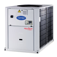
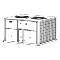
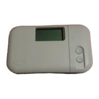
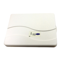
the specic unit. The cover images are solely for illustration and
form no part of any offer for sale or any sale contract.
IMPORTANT: All screenshots of the user interface provided
in this manual include text in English. After changing the
language of the system, all labels will be in the language
selected by the user.
Please read all instructions prior to proceeding with any work.
Pay attention to all safety warnings.
The information provided herein is solely for the purpose of
allowing customers to operate and service Carrier manufactured
equipment and it is not to be reproduced, modied or used for any
other purpose without the prior consent of Carrier Corporation.
In this manual, the refrigeration circuits are called circuit A and
circuit B. Compressors in circuit A are labelled A1, A2, A3, A4,
whereas compressors in circuit B are labelled B1, B2, B3, B4.
The following abbreviations are used frequently:
BMS Building Management System
CCN Carrier Comfort Network
DGT Discharge Gas Temperature
EMM Energy Management Module
EXV Electronic Expansion Valve
EHS Electric Heater Stage
FC Free Cooling
DCFC Dry Cooler Free Cooling
OAT Outdoor Air Temperature
LED Light Emitting Diode
LEN
Sensor Bus (internal communication bus
linking the basic board to slave boards)
SCT Saturated Condensing Temperature
SST Saturated Suction Temperature
VFD Variable Frequency Drive
Network mode/Net Operating type: Network
Local-Off/LOFF Operating type: Local Off
Local-On/L-C Operating type: Local On mode
Local-Schedule/L-SC
Operating type: Local On following a time
schedule
Master mode/Mast
Operating type: Master unit (master/slave
assembly)
Remote mode/Rem Operating type: Remote contacts
HSM Hydronic System Manager
ABBREVIATIONS
4
 Loading...
