6.9 - Capacity control
The control adjusts the capacity to keep the water exchanger
temperature at its setpoint. Compressors are started and stopped
in a sequence designed to equalise the number of start-ups (value
weighted by their operating time).
6.9.1 - Circuit loading sequence
This function determines in which order the circuit capacity is
changed. Compressor loading is managed by starting/stopping the
compressors. Two types of sequencing, i.e. balanced and staged
loading sequence, are available and can be congured by the user
via the user interface (GEN_CONF – General Conguration).
Balanced loading sequence: The control maintains equal
capacity between all circuits as the machine loads and unloads.
Balanced loading sequence is the default sequence employed by
the control.
Staged loading sequence: The control loads the lead circuit
completely before the lag circuits are started. When the load is
decreasing, the lag circuit is unloaded first. Staged loading
sequence is active when one of the circuits is shut down due to
its failure; the circuit is in capacity override mode; or the remaining
circuits are shut down or fully charged.
To set the circuit loading sequence
1. Navigate to the Conguration menu.
2. Select General Conguration (GEN_CONF).
3. Set Staged loading sequence [seq_typ].
Staged loading sequence [seq_typ]
No/Yes No
6.9.2 - Capacity for multi-circuit unit
The circuit lead/lag function determines the lead and lag circuit of
the unit. This function controls the start/stop sequence of two
refrigeration circuits called circuit A and circuit B.
The circuit authorised to start rst is the lead circuit. Lead circuit
is used rst for capacity increases and at the same time should
be decreased rst when decreasing capacity. The lead/lag circuits
can be selected manually or automatically (Cir Priority Sequence,
GEN_CONF – General Conguration).
■ Manual lead/lag circuit determination: Circuit A or circuit B
selected as the lead circuit. The selected circuit takes priority
over another circuit.
■ Automatic lead/lag circuit determination: The control system
determines the lead circuit to equalise the operating time of each
circuit (value weighted by the number of start-ups of each circuit).
As a result, the circuit with the lowest number of operating hours
always starts rst.
To set circuit priority
1. Navigate to the Conguration menu.
2. Select General Conguration (GEN_CONF).
3. Set Cir Priority Sequence [prio_cir].
Cir Priority Sequence [prio_cir]
0 Auto
1 Circuit A priority
2 Circuit B priority
6.10 - Night mode
Night mode allows users to congure the unit to operate with
specic parameters in a specic time period. During the night
period, the unit capacity is limited. The number of operating fans
is reduced (in cooling mode only).
The night period is dened by a start time and an end time that
are the same for each day of the week. The Night mode settings
or the maximum capacity value can be configured via the
Conguration menu (GEN_CONF – General Conguration). Only
logged-in users can modify the night mode settings.
To set the night mode
1. Navigate to the Conguration menu (logged-in users only).
2. Select General Conguration (GEN_CONF).
2. Set parameters corresponding to the night mode.
Night Mode Start Hour [nh_start]
00:00 to 24:00
Night Mode End Hour [nh_end]
00:00 to 24:00
Night Capacity Limit [nh_limit]
0 to 100% 100%
6.11 - Coil pressure control
The coil pressure of each circuit is managed by four fans maximum.
30RBM/RQM units are tted with xed speed fans and 30RBP/
RQP units are tted with variable speed fans providing higher part
load efciency and reduced acoustic levels.
In cooling mode, the condensing pressure is controlled
independently in each circuit based on the saturated condensing
temperature. The control permanently adjusts its setpoint to
guarantee optimal performance and ensure anti-short-cycle
protection of the fans.
In heating mode, the evaporating pressure is controlled independently
on each circuit based on the saturated suction temperature.
The control permanently adjusts its setpoint to guarantee optimal
performance, delay and limit frost accumulation on coils.
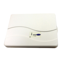
6.12 - Energy management module
The optional Energy Management Module is used to control the
level of energy consumption, providing users with information such
as current unit status, compressors operating status, etc.
For more information about connections associated with the
energy management module, see section 3.3.
6 - STANDARD CONTROL OPERATIONS AND OPTIONS
42
 Loading...
