PREFACE
The goal of this document is to give a broad overview of the main functions of the control system used to control 48/50 UC(V)-UP(V)
Rooftop air-air units with 25 to 220 kW cooling/heating capacity. Instructions in this manual are given as a guide to good practice in
the installation, start-up and operation of the control system. This document does not contain full service procedures for the correct
operation of the equipment.
The support of a qualified Carrier Service Engineer is strongly recommended to ensure optimal operation of the equipment as well
as the optimization of all available functionalities.
Note that this document may refer to optional components and certain functions, options or accessories may not be available for
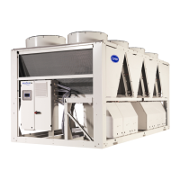
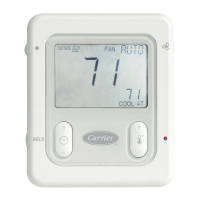
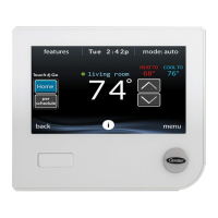
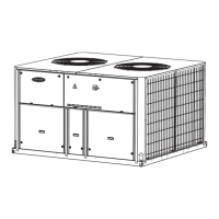
the specific unit. The cover images are solely for illustration and form no part of any offer for sale or any sale contract.
IMPORTANT: All screenshots of the user interface provided in this manual include text in English. After changing the language of the
system, all labels will be in the language selected by the user.
Please read all instructions prior to proceeding with any work. Pay attention to all safety warnings.
The information provided herein is solely for the purpose of allowing customers to operate and service Carrier manufactured
equipment and it is not to be reproduced, modified or used for any other purpose without the prior consent of Carrier Corporation.
ABBREVIATIONS
In this manual, the refrigeration circuits are called circuit A and
circuit B. Compressors in circuit A are labelled A1, A2, A3, A4,
whereas compressors in circuit B are labelled B1, B2, B3, B4.
Same for THR circuit which will be called circuit C.
The following abbreviations are used frequently:
 Loading...
