31
Unit Configuration Submenu
The UNIT sub-menu under the Configuration mode of the lo-
cal display contains general unit configuration items. The sub-
menu which contains these configurations is located at the lo-
cal display under Configuration
UNIT. See Table 32.
Machine Control Type (C.TYP)
This configuration defines the control type and control source
responsible for selecting a cooling, heating, or vent mode and
determines the method by which compressors are staged. The
control types are:
• C.TYP = 1 (VAV-RAT) and C.TYP = 2 ( VAV-SP T)
Both of these configurations refer to standard VAV opera-
tion. If the control is occupied, the supply fan is run contin-
uously and return-air temperature will be used in the
determination of the selection of a cooling mode. VAV-SPT
differs from VAV-RAT only in that during the unoccupied
period, space temperature will be used instead of return-air
temperature to start the fan for 10 minutes to establish an
accurate return-air temperature before the return-air
temperature is allowed to call out any mode.
• C.TYP = 3 (TSTAT-MULTI)
This configuration will force the control to monitor the ther-
mostat inputs to make a determination of mode. Unlike tra-
ditional 2-stage thermostat control, the unit is allowed to use
multiple stages of cooling control and perform VAV-type
operation. The control will be able to call out a LOW
COOL or a HIGH COOL mode and maintain a low or high
cool supply air setpoint.
• C.TYP = 4 (TSTAT-MULTI2)
This configuration will force the control to monitor the ther-
mostat inputs to make a determination of mode and allow
only multiple stages of control for both heating and cooling.
• C.TYP = 5 (SPT-MULTI)
This configuration will force the control to monitor a
space temperature sensor to make a determination of
mode. Unlike traditional 2-stage space temperature con-
trol, the unit is allowed to use multiple stages of cooling
control and perform VAV-type operation. The control will
be able to call out a LOW COOL or a HIGH COOL mode
and maintain a low or high cool supply air setpoint.
• C.TYP = 6 (SPT-MULTI2)
This configuration will force the control to monitor the
space temperature sensor to make a determination of mode
and allow multiple stages of control for both heating and
cooling.
Fan Mode (CV.FN)
The Fan Mode configuration can be used for machine control
types (Configuration
UNIT
C.TYP) 3, 4, 5, and 6. The
Fan Mode variable establishes the operating sequence for the
supply fan during occupied periods. When set to 1 (Continu-
ous), the fan will operate continuously during occupied peri-
ods. When set to 0 (Automatic), the fan will run only during a
heating or cooling mode.
Remote Switch Config (RM.CF)
The remote switch input is connected to TB6 terminals 1 and 3.
This switch can be used for several remote control functions.
Please refer to the Remote Control Switch Input section on
page 80 for details on its use and operation.
CEM Model Installed (CEM)
This configuration instructs the control to communicate with the
controls expansion module (CEM) over the Local Equipment
Network (LEN) when set to Yes. When the unit is configured for
certain sensors and configurations, this option will be set to Yes
automatically.
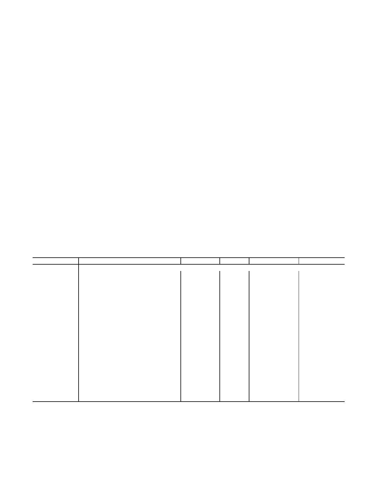
Table 32 — Unit Configuration
* For Design Series 4 units, only R410A is valid. If RFG.T is configured to
0 (R22) on Design Series 4 units, RFG.T will change it to 1 (R410A) and
will generate a system Alert indicating that R22 is not a valid option for
this point.
ITEM EXPANSION RANGE UNITS CCN POINT DEFAULTS
UNIT UNIT CONFIGURATION
C.TYP Machine Control Type 1 to 6 CTRLTYPE 4
CV.FN Fan Mode (0=Auto, 1=Cont) 0 to 1 FAN_MODE 1
RM.CF Remote Switch Config 0 to 3 RMTINCFG 0
CEM CEM Module Installed Yes/No CEM_BRD No
TCS.C Temp.Cmp.Strt.Cool Factr 0 to 60 min TCSTCOOL 0
TCS.H Temp.Cmp.Strt.Heat Factr 0 to 60 min TCSTHEAT 0
SFS.S Fan Fail Shuts Down Unit Yes/No SFS_SHUT No
SFS.M Fan Stat Monitoring Type 0 to 2 SFS_MON 0
VAV.S VAV Unocc.Fan Retry Time 0 to 720 min SAMPMINS 50
SIZE Unit Size (20 to 60) 20 to 60 UNITSIZE 20
DP.XR Discharge Press. Transducers Yes/No DP_TRANS No
SP.XR Suct. Pres. Trans. Type 0 to 1 SPXRTYPE 0
RFG.T* REFRIG: 0=R22, 1=R410A 0 to 1 REFRIG_T Unit dependent
CND.T CND HX TYP: 0=RTPF, 1=MCHX 0 to 1 COILTYPE Unit dependent
MAT.S MAT Calc Config 0 to 2 MAT_SEL 1
MAT.R Reset MAT Table Entries? Yes/No MATRESET No
MAT.D MAT Outside Air Default 0 to 100 % MATOADOS 20
ALTI Altitude……..in feet: 0 to 60000 ALTITUDE 0
DLAY Startup Delay Time 0 to 900 sec DELAY 0
STAT TSTAT-Both Heat and Cool Yes/No TSTATALL No
AUX.R Auxiliary Relay Config 0 to 3 AUXRELAY 0
SENS INPUT SENSOR CONFIG
SPT.S Space Temp Sensor Enable/Disable SPTSENS Disable
SP.O.S Space Temp Offset Sensor Enable/Disable SPTOSENS Disable
SP.O.R Space Temp Offset Range 1 to 10 SPTO_RNG 5
RRH.S Return Air RH Sensor Enable/Disable RARHSENS Disable
FLT.S Filter Stat.Sw.Enabled ? Enable/Disable FLTS_ENA Disable

 Loading...


