60
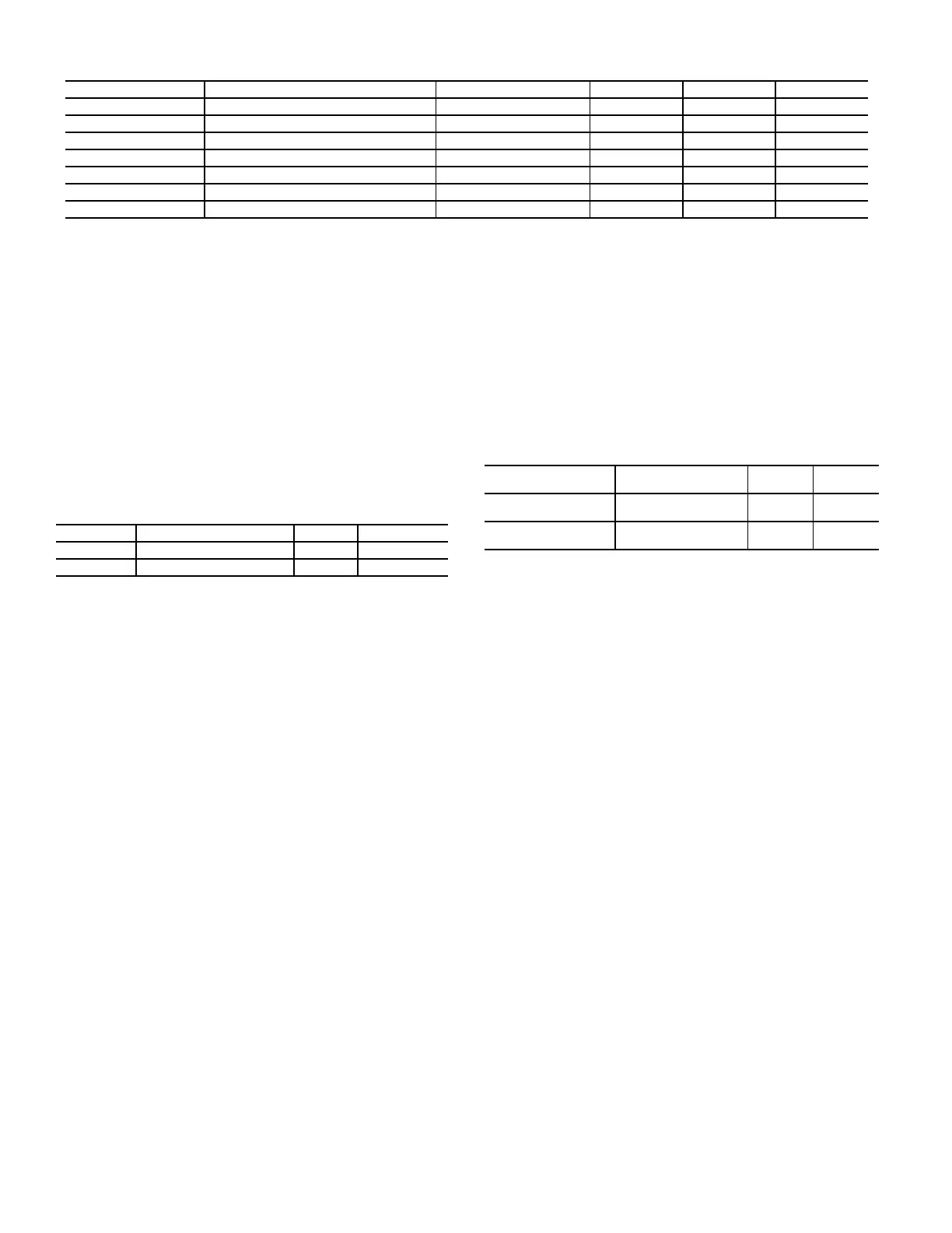
Table 60 — Static Pressure Reset Related Points
Fan Status Monitoring
GENERAL
The A Series ComfortLink controls offer the capability to de-
tect a failed supply fan through either a duct static pressure
transducer or an accessory discrete switch. The fan status
switch is an accessory that allows for the monitoring of a dis-
crete switch, which trips above a differential pressure drop
across the supply fan. For any unit with a factory-installed duct
static pressure sensor, it is possible to measure duct pressure
rise directly, which removes the need for a differential switch.
All 48/50A3,A5,A7,A9 units with a factory-installed supply
fan VFD will have the duct static pressure sensor as standard.
SETTING UP THE SYSTEM
The fan status monitoring configurations are located in Config-
uration
UNIT. See Table 61.
Table 61 — Fan Status Monitoring Configuration
Fan Stat Monitoring Type (SFS.M)
This configuration selects the type of fan status monitoring to
be performed.
0 - NONE — No switch or monitoring
1 - SWITCH — Use of the fan status switch
2 - SP RISE — Monitoring of the supply duct pressure.
Fan Fail Shuts Down Unit (SFS.S)
This configuration will configure the unit to shut down on a
supply fan status fail or simply alert the condition and continue
to run. When configured to YES, the control will shut down the
unit if supply fan status monitoring fails and the control will
also send out an alarm. If set to NO, the control will not shut
down the unit if supply fan status monitoring fails but will send
out an alert.
SUPPLY FAN STATUS MONITORING LOGIC
Regardless of whether the user is monitoring a discrete switch
or is monitoring static pressure, the timing for both methods is
the same and rely upon the configuration of static pressure con-
trol. The configuration that determines static pressure control is
Configuration
SP
SP.CF. If this configuration is set to 0
(none), a fan failure condition must wait 60 continuous sec-
onds before taking action. If this configuration is 1 (VFD), a
fan failure condition must wait 3 continuous minutes before
taking action.
If the unit is configured to monitor a fan status switch (SFS.M
= 1), and if the supply fan commanded state does not match the
supply fan status switch for 3 continuous minutes, then a fan
status failure has occurred.
If the unit is configured for supply duct pressure monitoring
(SFS.M = 2), then
• If the supply fan is requested ON and the static pressure
reading is not greater than 0.2 in. wg for 3 continuous min-
utes, a fan failure has occurred.
• If the supply fan is requested OFF and the static pressure
reading is not less than 0.2 in. wg for 3 continuous minutes,
a fan failure has occurred.
Dirty Filter Switch
The unit can be equipped with a field-installed accessory dirty
filter switch. The switch is located in the filter section. If a
dirty filter switch is not installed, the switch input is configured
to read “clean” all the time.
To enable the sensor for dirty filter monitoring set Configura-
tion
UNIT
SENS
FLT.S to ENABLE. The state of
the filter status switch can be read at Inputs
GEN.I
FLT.S. See Table 62.
Table 62 — Dirty Filter Switch Points
Monitoring of the filter status switch is disabled in the Service
Test mode and when the supply fan is not commanded on. If
the fan is on and the unit is not in a test mode and the filter sta-
tus switch reads “dirty” for 2 continuous minutes, an alert is
generated. Recovery from this alert is done through a clearing
of all alarms or after cleaning the filter and the switch reads
“clean” for 30 seconds.
NOTE: The filter switch should be adjusted to allow for the oper-
ating cfm and the type of filter. Refer to the accessory installation
instructions for information on adjusting the switch.
Economizer
The economizer control is used to manage the outside and re-
turn air dampers of the unit to provide ventilation air as well as
free cooling based on several configuration options. This sec-
tion contains a description of the economizer and its ability to
provide free cooling. See the section on Indoor Air Quality
Control on page 69 for more information on setting up and us-
ing the economizer to perform demand controlled ventilation
(DCV). See the Third Party Control section on page 25 for a
description on how to take over the operation of the economiz-
er through external control.
The economizer system also permits this unit to perform
smoke control functions based on external control switch in-
puts. Refer to the Smoke Control Modes section on page 68 for
detailed discussions.
Economizer control can be based on automatic control algo-
rithms using unit-based setpoints and sensor inputs. This econ-
omizer control system can also be managed through external
logic systems.
The economizer system is a factory-installed option. This unit
can also have the following devices installed to enhance econo-
mizer control:
• Outside air humidity sensor
• Return air humidity sensor
NOTE: All these options require the controls expansion module
(CEM).
ITEM EXPANSION RANGE UNITS CCN POINT DEFAULT
Inputs
4-20 SP.M Static Pressure mA 4 to 20 mA SP_MA
4-20 SP.M.T Static Pressure mA Trim -2.0 to +2.0 mA SPMATRIM
4-20 SP.R.M Static Pressure Reset mA 4 to 20 mA SPRST_MA 0.0
RSET SP.RS Static Pressure Reset 0.0 to 3.0 in. wg SPRESET 0.0
Outputs
Fans S.VFD Supply Fan VFD Speed 0 to 100 % SFAN_VFD
ITEM EXPANSION RANGE CCN POINT
SFS.S Fan Fail Shuts Down Unit Yes/No SFS_SHUT
SFS.M Fan Stat Monitoring Type 0 to 2 SFS_MON
ITEM EXPANSION RANGE
CCN
POINT
ConfigurationUNIT
SENSFLT.S
Filter Stat.Sw.Enabled ? Enable/
Disable
FLTS_ENA
InputsGEN.I
FLT.S
Filter Status Input DRTY/CLN FLTS

 Loading...


