13
INSTALLATION & CONNECTION
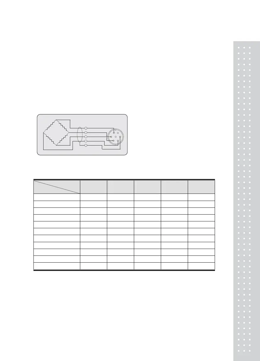
(1) Load Cell Connection
Pin 1: Excitation voltage+
Pin 2: Excitation voltage-
Pin 3: Sense voltage+
Pin 4: Sense voltage-
Pin 5: Shield
■ Connecting method
▶Ref. Each L/C
manufacturer's or model's
wire color could be
different. In that case,
please note the following
diagram.
■ Manufacturer's wire colors
Connector
Company
Pin 1
(EX+)
Pin 2
(EX-)
Pin 3
(SIG+)
Pin 4
(SIG-)
Pin 5
(GND)
CAS RED WHITE GREEN BLUE CASE
KYOWA RED BLACK GREEN WHITE CASE
INTERFACE RED BLACK GREEN WHITE CASE
P.T RED BLACK GREEN WHITE CASE
BLS GREEN BLACK WHITE RED YELLOW
SHOWA RED BLUE WHITE BLACK CASE
SHINKOH RED BLACK GREEN WHITE CASE
TMI RED WHITE GREEN BLUE YELLOW
TML RED BLACK WHITE GREEN CASE
TFAC RED BLUE WHITE BLACK YELLOW
HUNTLEIGH GREEN BLACK RED WHITE CASE
EX+
1
SIG+
SHIELD
SIG
-
EX
-
2
3
4
5
6
7