3 - SAFETY/DECALS
12
RR02K026
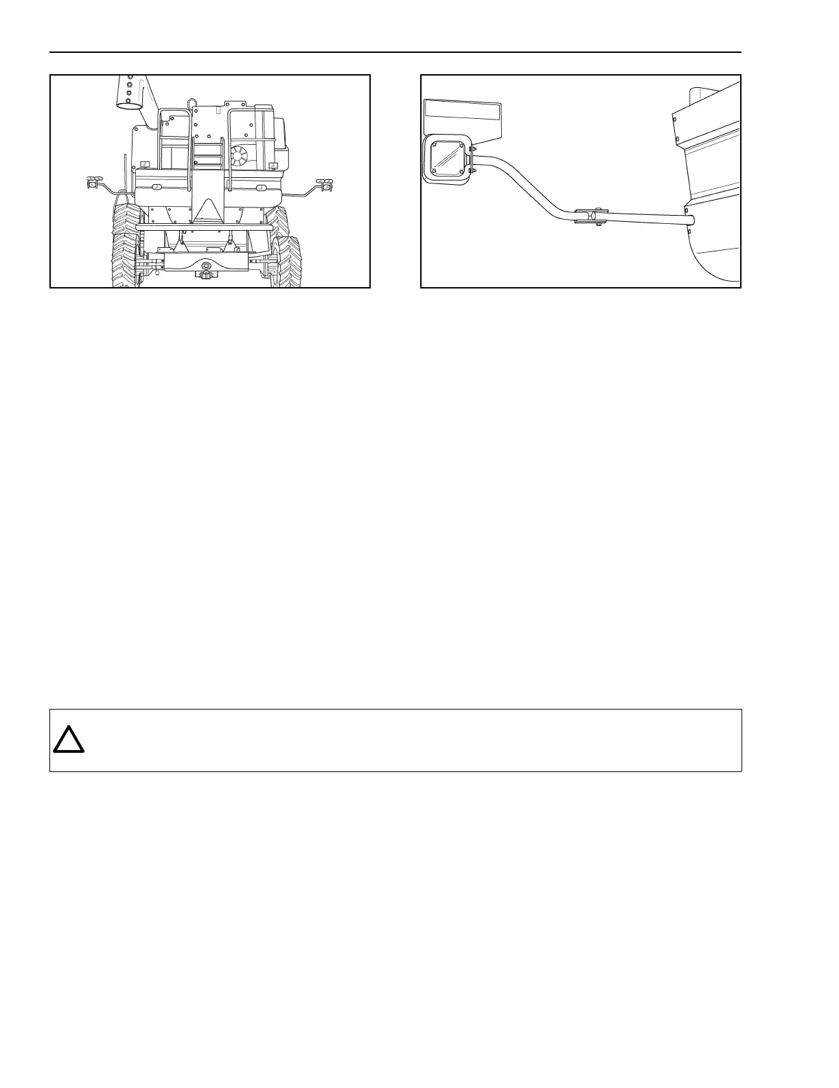
6. Make sure extremity warning lamp assemblies
are swung out to full width operating position.
Extremity warning lamps must be positioned
within 406 mm (16 inches) of outer edge of both
sides of Combine when the header is removed.
RD00H041
7. For dual drive wheel configurations extremity
warning lamp assemblies must be in the outer
position (inner edge of warning lamp assembly
tube flush with inner edge of mounting bracket
tube). Warning lamps must be positioned within
406 mm (16 inches) of outer edge of both sides
of Combine.
8. For flotation tires (76 x 50.00-32) drive wheel
configuration, extremity warning lamp
assemblies must be shifted an additional 127
mm (5 inches) outward per side (end of warning
lamp assembly tube recessed 127 mm (5 inches)
from end of mounting bracket tube). Warning
lamps must be positioned within 406 mm (16
inches of outer edge of both sides of Combine.
9. Check clearance before going under electric
lines, bridges or entering buildings.
10. Make sure the ladder is in the full forward or
transport position when in operation or traveling
on a road
WARNING: On narrow or hilly roads or blind curves - where motor vehicles can suddenly come upon slow
moving traffic, extra caution should be exercised, such as having two vehicles proceed/follow the Combine
to warn and/or removing the Header and transport separately.
M751
!
 Loading...