EasyManuals Logo

Casio QT-6000 Reference Manual

Casio QT-6000
210 pages
To Next Page IconTo Next Page
To Previous Page IconTo Previous Page
Page #15 background imageLoading...
Page #15 background image
R-15
QT-6000 Reference Manual
1-6. Input/output connectors
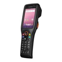
Power switch
Main power switch is located in the power switch cover.
Power switch cover
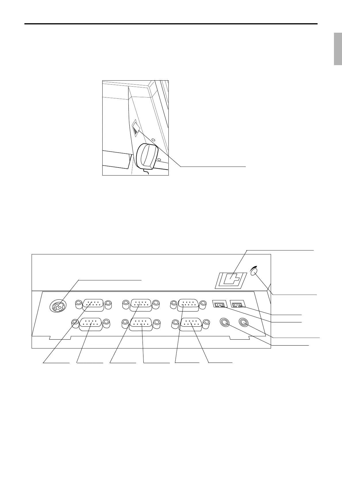
Input /output connectors
Inline connector, COM port, and drawer cable are located in the backside connector cover.
DC IN
PC/MODEM
SCANNER
DISPLAY
DRW1
DRW2
COM1
COM4
COM2
COM5
COM3
COM6
SPK
MIC
LAN1
VOL
COM1 COM4 COM2 COM5 COM3 COM6
From the AC adaptor
Inline (10/100Base-T)
Sound
volume control
Drawer 2
Drawer 1
Ext. microphone
Ext. speaker
Bottom side of the terminal

Table of Contents

Other manuals for Casio QT-6000

Questions and Answers:

Question and Answer IconNeed help?

Do you have a question about the Casio QT-6000 and is the answer not in the manual?

Casio QT-6000 Specifications

General IconGeneral
Types of paymentCash
Second displayYes
Second display typeLED
Power sourceAC
AC input voltage120-240 V
Power consumption1100 mA
Operating temperature (T-T)0 - 40 °C
Operating relative humidity (H-H)20 - 85 %
Weight and Dimensions IconWeight and Dimensions
Depth311 mm
Width343 mm
Height288 mm
Weight5300 g

Related product manuals