QW-5311
– 12 –12 ––
Cautions concerning Assembling
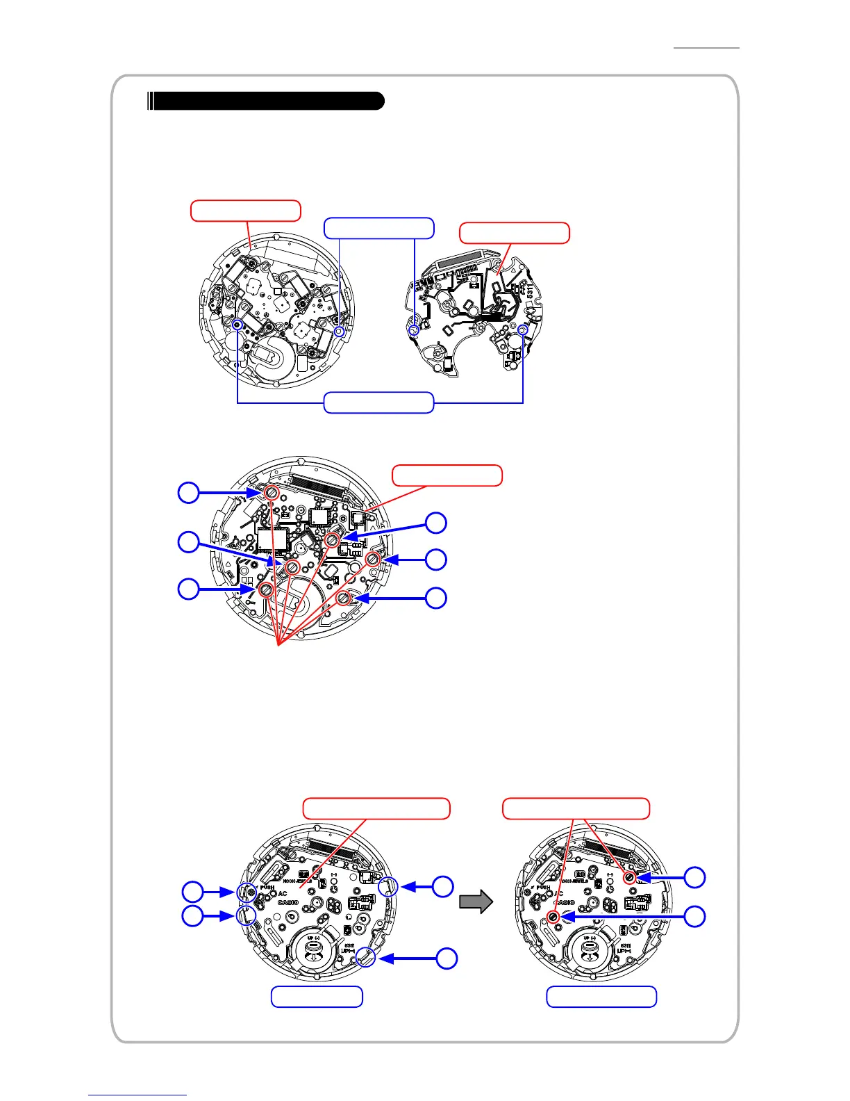
WheninstallingthePCBass’y,thecoilspringsmaylifttheass’y,causingdisposition.
BesurethatthePCBass’yispositionedcorrectly.
1) AligningtwoholesonthePCBass'ytothepinsontheanalogblock,pressthePCBass'ytothe
analogblock.
3H 9H
Align
Align
ANALOGBLOCK
PCB ass'y
2) InstalltheSCREW/FLAT4329intheordershowninthefollowingillustration.
2
6
3
1
4
5
SCREW/FLAT 4329 x 6
Tightening torque for the screws setting the PCB:
27.5 ± 2.5 mN
·m (280 ± 25.5 gf·cm)
PCB ass'y
3) Attachthecircuitsupporter5311totheanalogblockwithfourhooksintheordershowninthe
following illustration.
4)
InstalltheSCREW/FLAT2730intheordershowninthefollowingillustration.
3
2
1
2
1
1
Hooks
Circuit supporter 5311
SCREW/FLAT2730
SCREW/FLATs
 Loading...