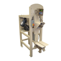
230 Series Auger Packer
16 OF 115
INSTALLATION PROCEDURES
Your system was assembled and tested in our factory. At disassembly, decals with match markings were
applied on matching parts to facilitate installation. Study the General Arrangement and other sub-
assembly drawings to determine the location of items. The center point of the packer inlet must be
located and marked on the floor; accomplish this by suspending a plumb bob from the center of the
mating supply hopper overhead. Verify that this center point on the floor is the proper distance from the
centerline of any associated equipment. Once this match has been verified, the packer can be put into
place and leveled.
NOTE: Do not anchor any equipment to the floor at this time. Equipment should be anchored to the floor
only after a satisfactory alignment and start-up has been achieved. Care must be taken in leveling the
packer at this point. After the packer has been placed in the desired operating location, level the packer
by plumbing the front legs. Any deviation from the plumb between the two legs should be compromised
half-way. This will result in plumb center lines. This step is important for the scale to function properly.
PNEUMATIC CONNECTIONS
Control air for the system should be supplied from a high pressure air source and should be clean and
dry. A minimum of 80 PSIG pressure at approximately 3-5 SCFM is required for proper operation of the
system. Air line connections must be ½” or larger. All air line connections should be made using a flexible
hose to minimize the transmission of vibration. Connect the pneumatic lines using the pneumatic
schematic and the color coded end connections.
ELECTRICAL CONNECTIONS
Control power for the system should be supplied from a clean power source and voltage verified to
ensure proper operation of the system.
NOTE: All wiring is to be accomplished in accordance with national electric code requirements. All
electrical connections should be made using a flexible type conduit to minimize the transmission of
vibration.
CAUTION: When drilling holes for conduit, make sure that absolutely no drill chips enter the panel, as
they may create a short circuit in the control circuits. Check all terminal block connections. Tighten those
which may have come loose during shipment. Connect all sensor and motor wires per the electrical
schematic and the color coded end connections. Terminations from the main electrical control panel to
junction boxes may be required per the electrical schematic. Connect the weighing system’s load cell
cable per the electrical schematic.
NOTE: To avoid the effects of electrical noise on the weighing system, avoid routing load cell cables near
any high voltage source.