Warning: Before connecting or disconnecting the unit check that power and control cables
are isolated from voltage sources.
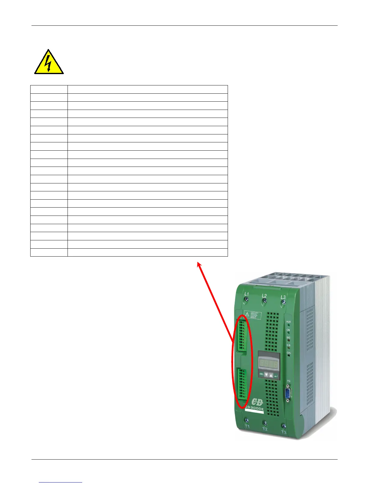
Terminal Description
1
Voltage Supply for Electronic Boards (See par. 12.2)
2
Voltage Supply for Electronic Boards (See par. 12.2)
3
Not used
4
Isolated output +12Vdc MAX 20mA
5
GND for Digital Input
6
Output +10Vdc MAX 5mA
7
GND for Analogue Input
8
(+)Analogue Input 1: Primary (See par. 12.3)
9
(+)Analogue Input 2: Ext. Current (See par. 12.3)
10
Analogue Output 1: Power (See par. 12.4)
11
RS485 B
12
RS485 A
13
Output relay: Run (Max 500mA, 125Vac)
14
Common of the contact relay: Run
15
NPN Output 1: Critical Alarm (12Vdc max 20mA)
16
NPN Output 2: Configurable (12Vdc max 20mA)
17
Digital Input: Reset Alarm
18
Digital Input: Start/Stop
19
Digital Input: Calibration
20
Digital Input: Configurable
(See par. 12)