Do you have a question about the CD Automation CD3000 E-3PH and is the answer not in the manual?
Unit's IP20 rating and earth connection for safety.
Dedicated voltage for electronics and risk of electric shock from capacitors.
Operational safety, EMC, and emissions guidelines.
Overview of the CD3000E's digital advantages over analog units.
Functionality and features of the CD-KP accessory.
CD-EASY for simple configuration backup and cloning.
Using the software for unit configuration and parameter management.
Formulas for calculating current based on load type and wiring.
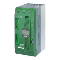
Locating and understanding the product identification label.
Detailed breakdown of the CD3000E order code options.
Guidelines for ambient temperature, humidity, and installation environment.
Physical dimensions and mounting hole specifications for different unit sizes.
Step-by-step instructions for removing the unit's cover.
General wiring precautions and power cable torque recommendations.
Recommended power cable sizing (mm² and AWG) for different currents.
Specification for command terminal wiring connection capacity.
Identification and function of power input (L1, L2, L3) and output (T1, T2, T3) terminals.
Detailed list of command terminals and their functions for Size S09.
Wiring diagram for the control connections of Size S09 units.
Detailed list of command terminals and their functions for Sizes S11/S13/S14.
Wiring diagram for the control connections of Sizes S11/S13/S14.
Graph illustrating current derating based on ambient temperature.
Information on the unit's cooling fans and their power consumption.
Table mapping LED indicators to unit status and alarms.
Explanation of critical alarms and their causes (Phase Loss, External, Over-temp).
Explanation of non-critical alarms (SCR Short Circuit, Unbalanced Load, Heater Break).
Steps for performing the unit calibration procedure.
Overview of control panel keys, display, and menu access.
Guide to selecting the appropriate firing mode for the load.
Details the Single Cycle firing method and its operational characteristics.
Recommended parameter settings for the Single Cycle firing mode.
Explains the Burst Firing method and its benefits for reducing interference.
Combines Burst Firing with soft start for reduced inrush current on inductive loads.
Recommended parameter settings for the Burst Firing mode.
Description of Phase Angle firing for inductive loads and transformer control.
Combines Phase Angle firing with soft start for transformer magnetization.
Recommended parameter settings for the Phase Angle firing mode.
How Delay Triggering prevents transient over-currents in transformer applications.
Recommended parameter settings for the Delay Triggering firing mode.
How the current limit controls output and the procedure to set it.
Explanation of available feedback modes (Voltage, Current, Power, External).
Mentions optional feedback configurations available on request.
Instructions for safely accessing the unit's internal electronic boards.
Requirements for supplying power to the unit's electronic boards and fans.
Overview of the two configurable analog inputs for setpoint and feedback.
How to configure and calibrate the primary analog input.
How to configure and calibrate the secondary analog input (Profiler/Feedback).
Details the analog output for average power retransmission.
Configuration of the average power analog output scaling.
Overview of the four opto-isolated digital inputs.
Functions of Reset Alarm, Start/Stop, Calibration, and Configurable digital inputs.
Overview of digital outputs (Relay and NPN).
Configuration of relay outputs for alarms and status.
Description of the connector used for software configuration.
Information on RS485 serial port for communication and networking.
Details the MODBUS RTU protocol and supported functions.
Structure and format of MODBUS messages, including CRC.
MODBUS function for reading parameter values.
MODBUS function for writing parameter values.
Explains error codes and exception responses in MODBUS communication.
How to set the unit's address for MODBUS communication.
Parameters for monitoring status, alarms, and basic settings.
Parameters for configuring analog inputs/outputs and communication settings.
Parameters for selecting firing type, feedback, and alarm settings.
Table of internal fuse types, ratings, and quantities.
Importance of fan operation and thermal switch protection.
Procedures for cleaning heat-sinks and checking terminals.
Details CD Automation's warranty policy for its products.
| Type | Thyristor Power Controller |
|---|---|
| Input | 3-phase |
| Output | 3-Phase |
| Frequency | 50/60 Hz |
| Operating Temperature | 0°C to 40°C |
| Humidity | 5% to 95% non-condensing |
| Protection | Overtemperature |
| Cooling | Forced Air |
| Storage Temperature | -25°C to 70°C |
| Dimensions | Varies depending on model |
| Weight | Varies depending on model |