CD Automation srl CD3000E-3PH from 25A to 500A User’s Manual
37
11.4.1 Suggested recipe for Delay Triggering
The firing type has already configured in line with customer requirements that are defined in the Order
Code. The Order Code is written on the identification label.
However, if you wish to change the firing type you can use the software configurator or the Control Panel
(see par. 10).
Caution: this procedure must be performed only by qualified persons.
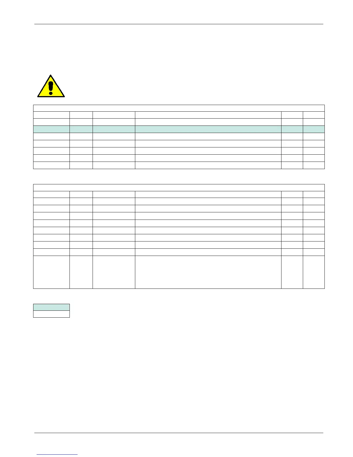
OPERATOR MENU
Parameter
Value Description UM Mode
0 Setpoint selection Analog/Digital R/W
P004 (H04)
Digital Setpoint value % R/W
P019 (H13)
100 Maximum Output % R/W
P024 (H18)
0÷1000² Setpoint Ramp Up Sec R/W
P025 (H19)
0÷1000² Setpoint Ramp Down Sec R/W
P116 (H74)
V Load Operative load voltage V R/W
P119 (H77)
I Load Load nominal current A R/W
SETUP MENU
Parameter
Value Description UM Mode
2 Firing Type R/W
P066 (H42)
20 HB sensitivity % R/W
P070 (H46)
1 Feed back selection R/W
P083 (H53)
8 Burst Firing Cycles (Not used in Phase Angle) Cycles
0 Ramp Cycles of Burst (Not used in Phase Angle) Cycles
0÷100³ Delay triggering ° R/W
P090 (H5A)
1 Limit current Analog/Digital R/W
P091 (H5B)
0÷100,0 Digital Limit current value % R/W
P098 (H62)
0÷3
Define the load type connection:
0=star
1=star+N
2=delta
3=open delta
R/W
= modification is not necessary
= modification is necessary
1 If the current limit is not used set this value to 100,0%.
² If don't use the setpoint ramp set this value to 0.
³ The delay angle suggest for most applications is 80°