18
cdvigroup.com
A22K
High Security Access Control 2-Door Module
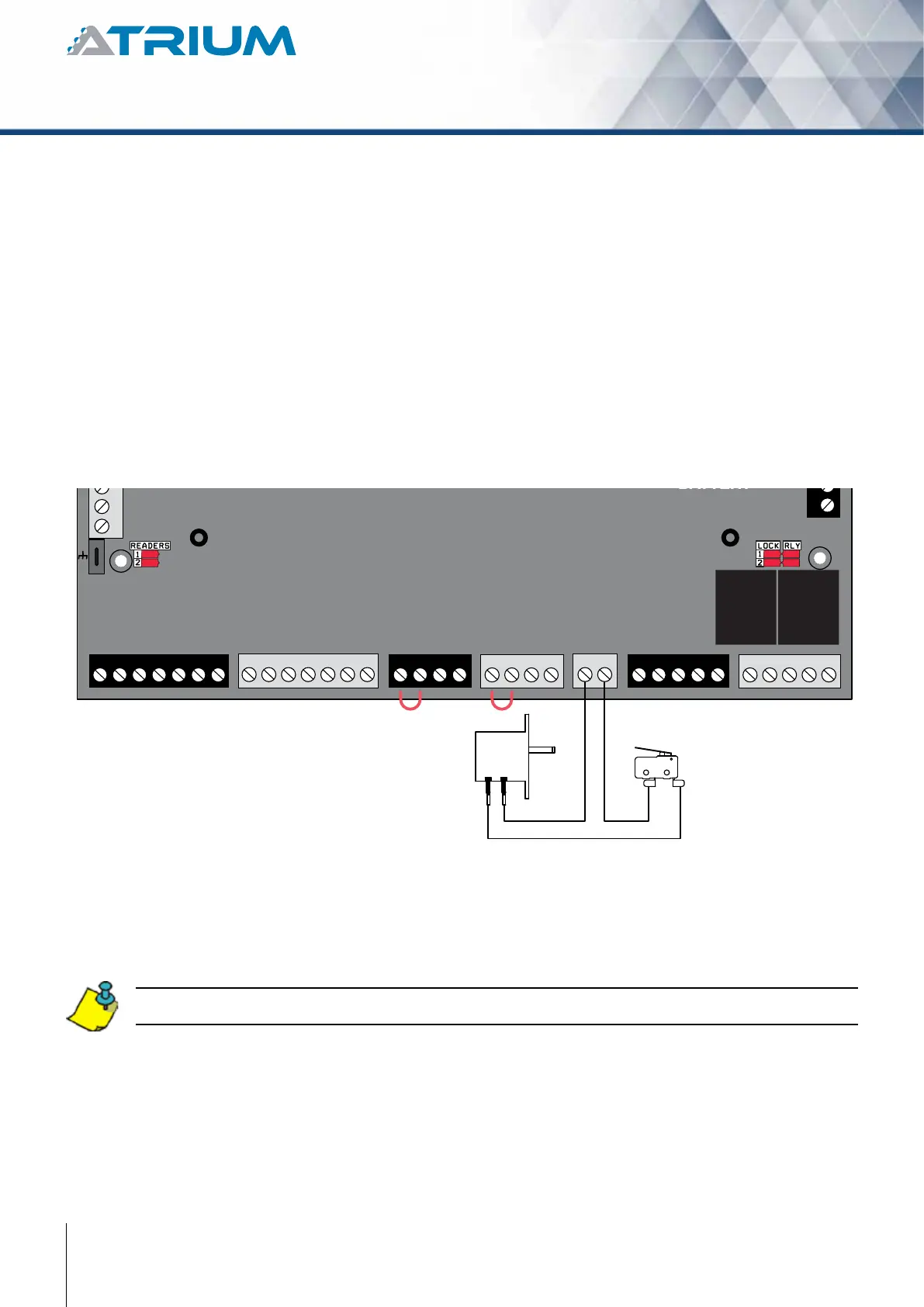
Connecting the tamper switches allows the A22K to detect when the cabinet door is opened and/or when the
cabinet is removed from the wall. To install the tamper switches, see “Installing the Tamper Switches”.
To use both switches:
1. Connect one end of the supplied wire to the door tamper switch
terminal and the other end to the wall tamper switch terminal.
2. Connect the other terminal of the door tamper switch to the “TMP” terminals using the
supplied wire.
3. Connect the other terminal of the wall tamper switch to the “GND” terminals using the
supplied wire.
To use only one switch:
1. Connect one terminal of the tamper switch to the “TMP” terminals using the supplied wire.
2. Connect the other terminal of the same tamper switch to the “GND” terminals using the
supplied wire.
If you do not use the tamper switch, connect a wire between the “TMP” and “GND” terminals.
-
+12V DC
A+
B-
Input 1
Input 2
Output 1
Output 2
INPUT
POWER
SUPPLY
RS485
LOCAL
BUS
ETHERNET
PORT
SYSTEM STATUS
EXTRA
INPUTS/
OUTPUTS
ETHERNET LOCAL BUS LOCK 1 & 2
JUMPER SETTING
STATUS
24V DC INPUT/
BATTERY/
MODULE TYPE
BATTERY
BACKUP
Metal Box
Door Tamper Switch
(N.C.)
Metal Box
Wall Tamper Switch
(N.C.)
READER DOOR 1
INPUT
DOOR 1
LOCK
DOOR 1
LOCK
DOOR 2
INPUT
DOOR 2READER DOOR 2
ENCLOSURE
TAMPER
SWITCH
INPUT
BUZ GRN RED D1 D0 GND 12V BUZ GRN RED D1 D0 GND GNDC112V 12VREX1 GND GND C1 NO1 NC1LK1+ LK1- C2 NO2 NC2LK2+ LK2-TMPC2 12VREX2