19
cdvigroup.com
A22K
High Security Access Control 2-Door Module
READERS AND KEYPADS
The A22K allows automatic format detection and decoding of the connected reader/keypad. When installing a
keypad with a Wiegand output, the keypad’s “D0” and “D1” wires should be connected to the same terminals as
the reader (the reader or keypad LED and buzzer outputs must be open collector).
The ATRIUM system is congured by default for the K1, NANO, STAR and SOLAR reader models which display
a bright blue backlight in standby mode. Other popular Wiegand readers and keypads are also supported.
Contact us to conrm compatibility. Most readers and keypads have built-in buzzers and LEDs. These should be
connected to module’s programmable outputs (B1, G1, R1 for READER 1 and B2, G2, R2 for READER 2). These
are open collector outputs capable of sinking 100mA. Please note that the B, G and R outputs are programmed
for a 7-wire reader by default.
LED indicator is steady blue
LED indicator changes from blue to green
LED indicator changes from blue to ashing red
LED indicator changes from blue to brief green
Typically, the reader buzzer or an external sounding device will inform the card user that the door has
been left open after a valid access or the door has been forced open. The functions of all these outputs are
programmable through the ATRIUM software.
(Showned with K1 Reader)
+12V DC
+24V DC
-
+12V DC
-
+12V DC
A+
B-
Input 1
Input 2
Output 1
Output 2
INPUT
POWER
SUPPLY
RS485
LOCAL
BUS
ETHERNET
PORT
SYSTEM STATUS
EXTRA
INPUTS/
OUTPUTS
READER DOOR 1
INPUT
DOOR 1
LOCK
DOOR 1
LOCK
DOOR 2
INPUT
DOOR 2READER DOOR 2
ETHERNET LOCAL BUS LOCK 1 & 2
JUMPER SETTING
STATUS
24V DC INPUT/
BATTERY/
MODULE TYPE
BATTERY
BACKUP
ENCLOSURE
TAMPER
SWITCH
INPUT
K1 K1
ENTRY EXIT
Red
Black
Green
White
Red
Blue wire
not used
Black
Green
White
Blue wire
not used
Blue wire to
A22K GND terminal
IMPORTANT:
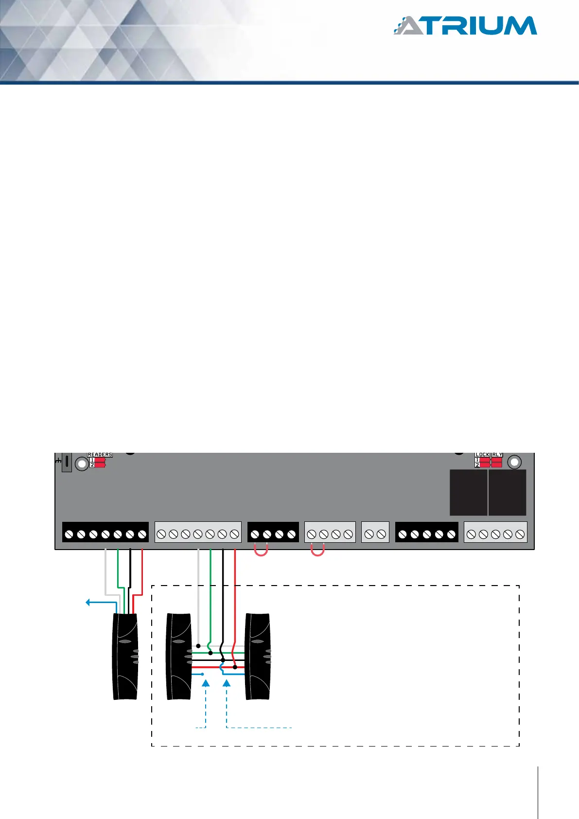
That option can ONLY be done with CDVI
RS485 high security card readers.
OPTION OF ENTRY/EXIT READERS
ON THE SAME PORT
BUZ GRN RED D1 D0 GND 12V BUZ GRN RED D1 D0 GND GNDC112V 12VREX1 GND GND C1 NO1 NC1LK1+ LK1- C2 NO2 NC2LK2+ LK2-TMPC2 12VREX2