30
cdvigroup.com
A22K
High Security Access Control 2-Door Module
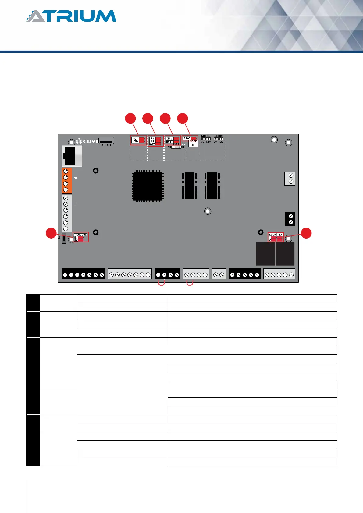
The ATRIUM A22K has several status LEDs that are very useful to diagnose the ATRIUM system. Refer to the
following picture to locate the LEDs on the ATRIUM A22K.
+12V DC
+24V DC
-
+12V DC
-
+12V DC
A+
B-
Input 1
Input 2
Output 1
Output 2
INPUT
POWER
SUPPLY
RS485
LOCAL
BUS
ETHERNET
PORT
SYSTEM STATUS
EXTRA
INPUTS/
OUTPUTS
ETHERNET LOCAL BUS LOCK 1 & 2
JUMPER SETTING
STATUS
24V DC INPUT/
BATTERY/
MODULE TYPE
BATTERY
BACKUP
1
5
6
2 3 4
READER DOOR 1
INPUT
DOOR 1
LOCK
DOOR 1
LOCK
DOOR 2
INPUT
DOOR 2READER DOOR 2
ENCLOSURE
TAMPER
SWITCH
INPUT
BUZ GRN RED D1 D0 GND 12V BUZ GRN RED D1 D0 GND GNDC112V 12VREX1 GND GND C1 NO1 NC1LK1+ LK1- C2 NO2 NC2LK2+ LK2-TMPC2 12VREX2
1
ETHERNET ACT Green LED ashing: Data transmitted/received.
LNK Steady Green LED: Ethernet network detected.
2
LOCAL BUS RX Green LED ashing: Data received on local bus.
TX Green LED ashing: Data transmitted on local bus.
12V Steady Green LED: 12V on local bus.
3
24Vdc Input
/ Battery
24V Steady DC IN Green LED: A22K is powered properly.
Red LED: No primary power.
BATT Green LED: On primary power present and battery charging.
Green LED O Steady: Primary power present and battery full.
Red LED: No battery or battery not properly connected.
Red LED ashing: Battery power is below 11.8Vdc.
4
STATUS STAT Flash once per second: Firmware is operating normally.
Flash rapidly: Firmware is upgrading.
Blink once per 3 seconds: Card enrollment mode.
5
READERS #1 Green LED ashing: Data received from Reader #1.
#2 Green LED ashing: Data received from Reader #2.
6
LOCK &
RELAY
LOCK 1 Green LED: Door 1 Lock Relay is active/triggered.
LOCK 2 Green LED: Door 2 Lock Relay is active/triggered.
RLY1 Green LED: Auxiliary Relay 1 is active/triggered.
RLY2 Green LED: Auxiliary Relay 2 is active/triggered.