28
cdvigroup.com
A22K
High Security Access Control 2-Door Module
+12V DC
+24V DC
-
+12V DC
-
+12V DC
A+
B-
Input 1
Input 2
Output 1
Output 2
INPUT
POWER
SUPPLY
RS485
LOCAL
BUS
ETHERNET
PORT
SYSTEM STATUS
EXTRA
INPUTS/
OUTPUTS
ETHERNET LOCAL BUS LOCK 1 & 2
JUMPER SETTING
STATUS
24V DC INPUT/
BATTERY/
MODULE TYPE
BATTERY
BACKUP
Ethernet @ 10/100 Mbps
Maximum 100m (300ft.)
Red
Power Supply
LED Indicator
White
PoE+ Splitter
POES
From PoE+ source
(Data + Power)
Ethernet Port
(Data)
DC power output
(24 Vdc)
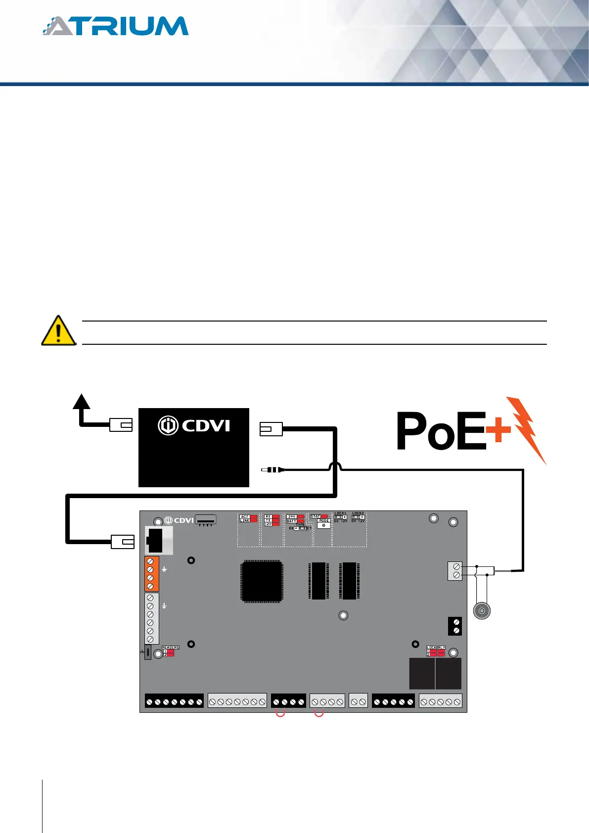
The pre-assembled PoE+ Splitter
seperate data and power coming
from PoE+ source, example:
PoE+ switch or injector
READER DOOR 1
INPUT
DOOR 1
LOCK
DOOR 1
LOCK
DOOR 2
INPUT
DOOR 2READER DOOR 2
ENCLOSURE
TAMPER
SWITCH
INPUT
BUZ GRN RED D1 D0 GND 12V BUZ GRN RED D1 D0 GND GNDC112V 12VREX1 GND GND C1 NO1 NC1LK1+ LK1- C2 NO2 NC2LK2+ LK2-TMPC2 12VREX2
Do not power up the A22POE until all connections are completed.
The PoE+ splitter to DC power supply is pre-installed in the A22KPOE box but needs to be connected to the
PCB. Simply plug the two pin terminal to the input power supply.
See “Recommended Wiring” section for more information on wiring type, size, and maximum length.
Power Over Ethernet
Interface
• 2-PortRJ-45interfaces
-1-PortData+Powerinput
-1-PortDataoutput
• 1-PortDCoutputpowersocket
• Outputsetto24VDC(DIPswitch)
Power over Ethernet
• UltraPoweroverEthernetEnd-Span/Mid-SpanPSE
• IEEE802.3at/afPoEstandardcompliant
• Supports56VDC,50pwaPoEpoweroutput
• Splitsthe56VDCpoweroverRJ-45Ethernetcableinto24VDC
output
• Remotepowerfeedingupto100meters