14
cdvigroup.com
CTV900A
2-Door Controller
INSTALLATION MANUAL
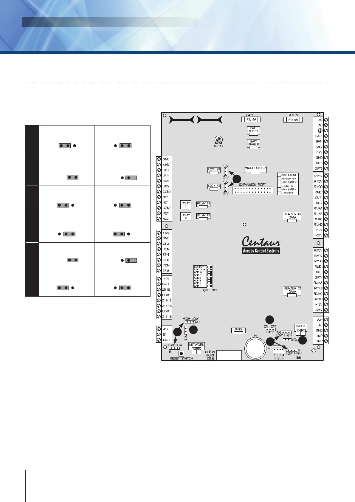
5] WIRING DIAGRAM
JUMPER SETTINGS
CTV900A
2-Door Controller
1
2
3
5
6
4
1
Backup battery ON
ON OFF
BATT
Backup battery OFF
ON OFF
BATT
2
Network EOL ON
EOL
Network EOL OFF
EOL
3
Network A+ & B- HIGH
HIGH LOW
Network A+ & B- LOW
HIGH LOW
4
Lock output 12V
24V 12V
Lock output 24V
24V 12V
5
E-BUS EOL ON
EOL
E-BUS EOL OFF
EOL
6
E-BUS A+ & B- HIGH
HIGH LOW
E-BUS A+ & B- LOW
HIGH LOW
BATT ON/OFF
When the jumper is on, the controller enables the RAM and RTC battery backup (default = o). Once the
controller is installed, the jumper must be on for correct operation. If you are required to replace the 3V backup
battery, we recommend that you set the jumper to o until the the battery is replaced. If a complete power loss
occurs, the time and date as well as all controller programming will be lost.