33
cdvigroup.com
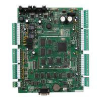
CTV900A
2-Door Controller
INSTALLATION MANUAL
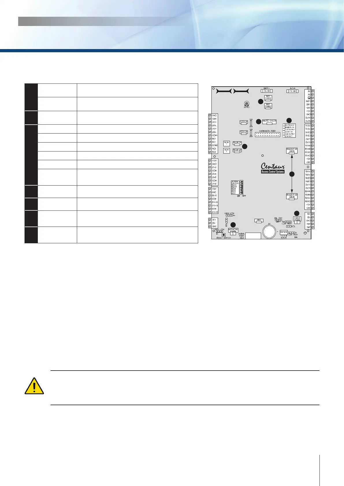
LED INDICATORS
CTV900A
2-Door Controller
3
1
2
4
6
7
5
1
BATT CHECK
During a battery test, the “BATT CHECK” LED
should be on for four seconds
BATT ENABLE
When there is a complete loss of power (no AC or
battery), the “BATT ENABLE” LED should be o.
2
MICRO CHECK
LED ashes every 750ms in normal operation or
every 350ms if communication fails.
3
AC PRESENT LED on: AC is present
READER +5V LED on: Output power activated.
+12V SUPPLY LED on: Output power activated.
LOGIC +5V LED on: Microprocessor power activated.
+24V SUPPLY LED on: Output power activated.
LOW BATT
Low batery @ 20.5V, LED will ash.
Low Battery cut-o @ 16.8V
4
RELAY 1 and 2 LED on: Relay is active/triggered
5
READER DATA LED on: Data received from Reader
6
LOCAL BUS
RX: LED ashing: Data received on local bus.
TX: LED ashing: Data transmitted on local bus.
7
NETWORK
RX: LED ashing: Data received on network.
TX: LED ashing: Data transmitted on network.
UPON POWER UP
• The “AC PRESENT” LED should be on.
• The “READER 5 VOLT” LED should be on.
• The “12 VOLT SUPPLY” LED should be on.
• The “LOGIC 5 VOLT” LED should be on.
• The “MICRO CHECK” LED ashes every 750ms in normal operation or every 350ms if
communication fails.
• When a valid card is presented at either reader, the LED indicator associated with the reader
activates for 750ms.
• When a card is presented to a reader that does not conform to the programmed format, the LED
indicator associated with the reader will activate for 100ms.
If the “micro check”, “low bat”, “reader 1” and “reader 2” LEDs are ashing in a circular manner, the
controller has no rmware and must be updated. The update can be done from the rmware update
application which can be downloaded from our web site. For more information refer to the Centaur.
Operator’s Manual or visit our web site at www.cdvigroup.com