24
cdvigroup.com
CTV900A
2-Door Controller
INSTALLATION MANUAL
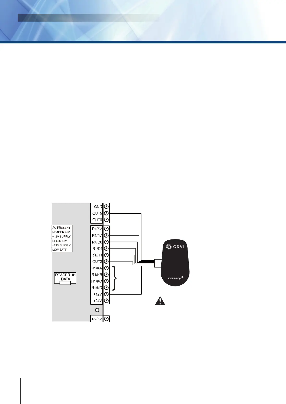
PROGRAMMABLE OUTPUTS
Most readers and keypads have built-in buzzers and LEDs. These should be connected to controller’s
programmable outputs (OUT1 to OUT6) as shown below. These are open collector outputs capable of sinking
25mA with a 10Ω limiting resistor. For information on how to program the outputs, please refer to the Centaur
Operator’s Manual. The settings are as follows:
• Output 1: (Default: Door 1 Green LED)
• Output 2: (Default: Door 1 Red LED)
• Output 3: (Default: Door 2 Green LED)
• Output 4: (Default: Door 2 Red LED)
• Output 5: (Default: Door 1 Buzzer/Piezo)
• Output 6: (Default: Door 2 Buzzer/Piezo)
Typically, a red/green indicator on the reader will inform the card user that access has been granted (changes
from red to green), access has been denied (ashing red), or the door is locked (solid red). Typically, the reader
buzzer or an external sounding device will inform the card user that the door has been left open after a valid
access or the door has been forced open. The functions of all these outputs are programmable through the
Centaur software.
CTV900A
2-Door Controller
TAMPER
TAMPER
Keypad
1
Reader and keypad
wiring may differ
from diagram.
Please consult your
dealer for details.
NANOPB
Mini
Proximity
Reader 1
Red
Black
Green
White
Orange
Yellow
Brown