29
cdvigroup.com
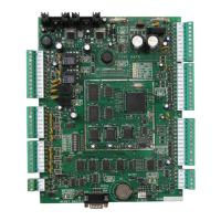
CTV900A
2-Door Controller
INSTALLATION MANUAL
DOOR - LOCKING DEVICES
Each controller has two lock outputs and each of these outputs is associated to a reader input. Using the lock
output jumpers you can set each lock output to provide 12VDC or 24VDC (see “Jumper Settings”). A lock
output voltage of 24VDC is recommended for most locking devices. Lock outputs are protected by fuseless
technology and will shutdown if the current exceeds 800mA @ 12/24VDC.
• If you have one door with a reader on each side of the door, you can use either lock output.
• You can program the lock outputs to function in “fail-safe” (remove power to unlock a door) or “fail-
secure” mode (power required to unlock a door).
• When using Electronic Mag Clamps or similar devices ensure that the current specications are not
exceeded.
• When interconnection to a re alarm system is required, we recommend the CAA110P Lock Control
Module. This module can be used to cut power to the locks during a re alarm. Refer to the
module’s installation instructions for connection of the CAA110P device.
Always consult the regulatory agency in your area for existing regulations regarding doors designated
as emergency exits.
Connecting Locking Devices
RELAYS
Each controller has two 30VDC, 110VAC, 5A resistive form “C” relays with a “normally open” and a “normally
closed” contact. These relays can be used to activate alarm sounders or other devices such as lighting control,
air conditioning. An additional 14 relays can be added per controller by connecting two CAA460P Relay
Expansion modules to the controller’s E-Bus. The relays can be programmed to activate or deactivate according
to a schedule, input or event.