30
cdvigroup.com
CTV900A
2-Door Controller
INSTALLATION MANUAL
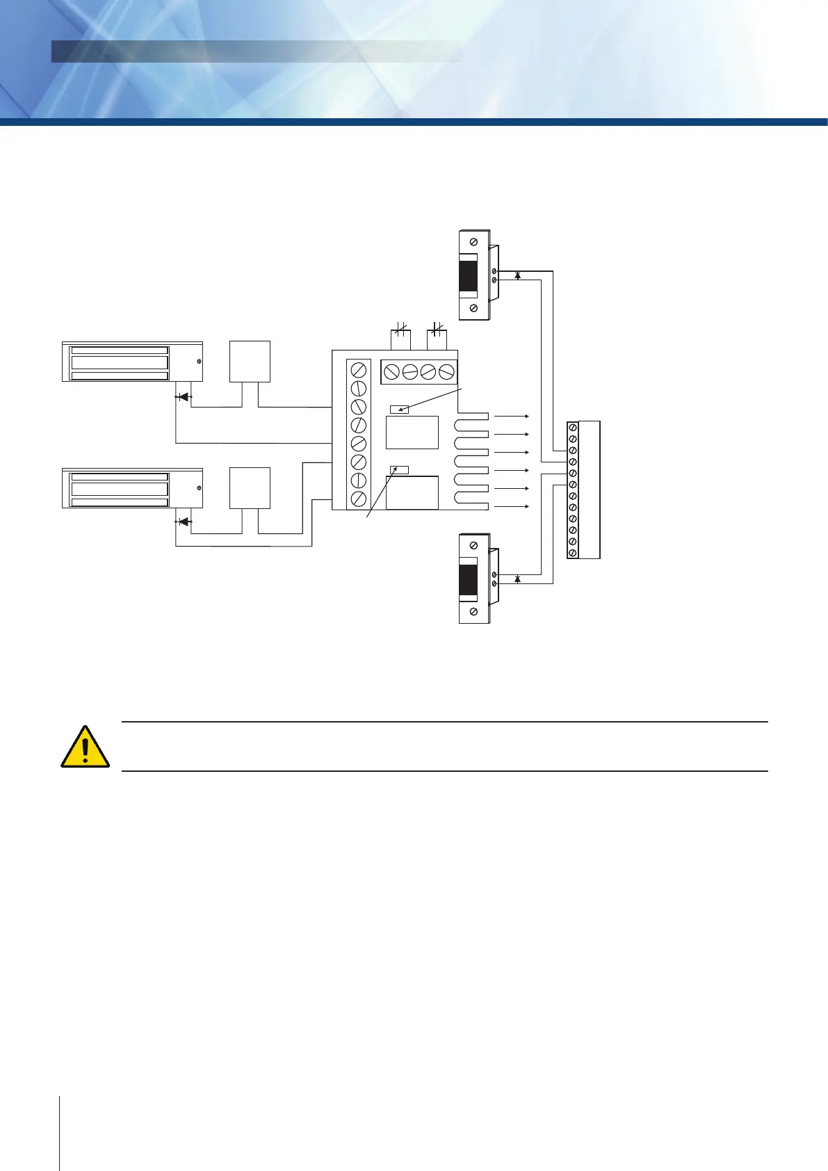
See “Recommended Wiring” section for more information on wiring type, size, and maximum length.
The power source for the separated energized locking devices shall be a UL/ULC listed burglar alarm
or access control system power supply.
NO1
NC1
NO2
NC2
COM1
COM2
LK1+
LK1-
LK2+
LK2-
+24V
GND
Relay 1
GND
GND
LK1+
LK2+
LK1-
LK2-
+24V
UNLK1
LED1
Relay 1 activation
LED (Green)
LED2
UNLK2
+24V
C1 C2NO1 NO2NC1 NC2
Relay 2
Fire alarm contact
for Lock 1
Fire alarm contact
for Lock 2
Electromagnetic Lock 1
Electromagnetic Lock 2
Power Supply
Power Supply
Door Strike 1
Door Strike 2
Important Note:
The CAA110P relays are rated at 12VDC,
therefore, using the appropriate jumper
settings, set the CTV900A lock output voltage
to 12VDC. Higher voltage will damage the
CAA110P module and void the warranty.
+
-
+
+
-
-
+
-
+
-
+
-
Note: The relays, which are used to control power to
the electromagnetic locks, are toggled by the activation
of the controller’s lock terminals or the CAA110P’s fire
alarm contact inputs.
Relay 2 activation
LED (Green)
Connecting Locking Devices using CAA110P Lock Control Module